semi合集-English.pdf - 第125页
SEMI E17-0600 © SEMI 1991 , 2000 1 SEMI E17-0600 GUIDELINE FOR MA SS FLOW CONTROLLER TR ANSIENT CHARACTERISTICS TESTS This g u ideline was tec hnically approved by the Global Fa cilities Committee and is the direct respo…

SEMI E16-90 © SEMI 1990, 2004 3
Interval Rate Example
t1 Initial System Response Less than 10 seconds
t2 Leak Prior to Onset of
Permeation
w1 10 seconds to 1 minute
t3 Increasing Permeation 1 minute to 30 minutes
t4 Total Saturation w2 Beyond 30 minutes
Figure 4
Leak Detector Output Value vs. Time
4.3.1 The actual shape of these curves and time
intervals is dependent on the design of the MFC under
test, the elastomer used, if any, and the characteristics
of the leak detection system. These time intervals must
be determined using sound engineering judgment
following qualification testing of the specific MFC
model and test set-up. Once determined, it is
recommended that receiving inspection consist of
measuring for leak rate value w1 at the end of interval
t2.
4.3.2 Following qualification testing, report typical
values for t1 through t4 and w1 and w2. w1 is primarily
the mechanical portion of the leak, and w2 is
mechanical plus permeation. In the case where w2 is
significantly greater than w1, w2 is primarily
permeation. In the case of a gross mechanical leak, w1
could greatly exceed, and thereby mask, w2.
NOTE 3: This test must be performed with elastomers that
are devoid of helium. Such elastomers have either not been
previously exposed to helium or have been degassed
following exposure. Once this test has been performed, the
elastomers must be purged of helium by the passage of time
and/or baking.
4.3.3 In good leak testing practice, the background
level should be verified before the application of helium
to ensure that the elastomers are in a helium degassed
state and that the leak detecting system is in proper
operation.
NOTICE: SEMI makes no warranties or
representations as to the suitability of the standards set
forth herein for any particular application. The
determination of the suitability of the standard is solely
the responsibility of the user. Users are cautioned to
refer to manufacturer's instructions, product labels,
product data sheets, and other relevant literature,
respecting any materials or equipment mentioned
herein. These standards are subject to change without
notice.
By publication of this standard, Semiconductor
Equipment and Materials International (SEMI) takes no
position respecting the validity of any patent rights or
copyrights asserted in connection with any items
mentioned in this standard. Users of this standard are
expressly advised that determination of any such patent
rights or copyrights, and the risk of infringement of
such rights are entirely their own responsibility.
Copyright by SEMI® (Semiconductor Equipment and Materials
International), 3081 Zanker Road, San Jose, CA 95134. Reproduction of
the contents in whole or in part is forbidden without express written
consent of SEMI.

SEMI E17-0600 © SEMI 1991, 20001
SEMI E17-0600
GUIDELINE FOR MASS FLOW CONTROLLER TRANSIENT
CHARACTERISTICS TESTS
This guideline was technically approved by the Global Facilities Committee and is the direct responsibility of
the North American Facilities Committee. Current edition approved by the North American Regional
Standards Committee on April 10, 2000. Initially available at www.semi.org April 2000; to be published
June 2000. Originally published in 1991.
1 Scope
1.1 This guideline is intended to establish a common
basis for communication between users and suppliers of
semiconductor equipment. It provides terminology and
methodology aimed at eliminating confusion regarding
what previously has been referred to as MFC “response
time.” The conditions and procedures are given for
determining and expressing the transient characteristics
of a mass flow controller (MFC) to a step change in set
point. This guideline applies to mass flow controllers
for gases used in semiconductor fabrication equipment.
1.2 This guideline does not purport to address safety
issues, if any, associated with its use. It is the
responsibility of the users of this guideline to establish
appropriate safety and health practices and determine
the applicability of regulatory limitations prior to use.
2 Definitions (Figures 1 and 2)
2.1 Actual Flow — For the purpose of this standard,
the output value of the master reference standard.
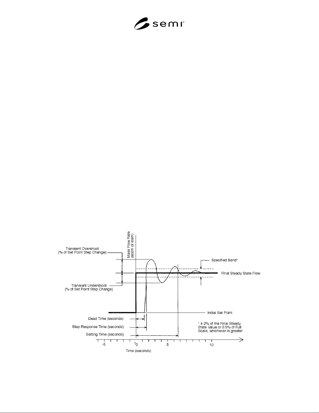
2.2 Dead Time — The interval of time between the set
point step change and the start of the resulting
observable response.
2.3 Final Steady State Value — The average value of
the actual flow, after the effects of the input transient
have expired to a value equal to or below the intrinsic
drift and noise.
2.4 Settling Time — The time between the set point
step change and when the actual flow remains within
the specified band.
2.5 Step Response Time — The time between the
setpoint step change and when the actual flow first
enters the specified band.
2.6 Transient Overshoot — The maximum change in
actual flow minus the steady state change in actual
flow, expressed as a percentage of the set point step
change.
2.7 Transient Undershoot — The maximum amount
that the actual flow passes the final steady state value,
in the opposite direction of overshoot, expressed as a
percentage of the set point step change.
2.8 Set Point — The electrical input signal to the MFC
which sets the desired value of the controlled flow.
2.9 Specified Band — The region between ± 2% of the
final steady state value or ± 0.5% of full scale,
whichever is greater.
3 Test Setup
3.1 The purpose of the flow system is to furnish the
mass flow controller under test with a constant pressure
supply of suitable gas. It must also provide a means of
determining the gas flow rate through the mass flow
controller that responds to changes in gas flow
significantly faster than the device under test. The
recommended flow system for testing the speed of
response of MFCs is shown in Figure 3a.
3.2 The flow system shall have straight tubing or pipe
connecting the MFC to the master reference standard.
The inside diameter of the interconnecting tubing or
pipe shall be of sufficient size to preclude any pressure
drop that would affect the performance of the MFC.
3.3 The pneumatic time constant, Tau, should be
minimized. (See Section 3.7.)
Tau = (V*DPm) / (Qm*Pa)
Where:
V = Internal volume of the flow system between the
MFC under test and the master reference standard,
including tubing, fittings and the side of the master
reference standard that is connected to the MFC
under test.
Qm = Maximum volumetric flow expected during the test.
DPm = Pressure drop of the master reference standard at
flow Qm.
Pa = The absolute pressure present at the outlet of the
master reference standard at final steady state value.
3.4 The source of the test gas shall be capable of
delivering an essentially constant upstream pressure to
the mass flow controller under test during the transient
characterization. A maximum variation of ± 2% from
SEMI E17-0600 © SEMI 1991, 2000 2
the median absolute pressure is considered adequate for
most mass flow controllers.
3.5 Nitrogen is the recommended gas for the standard
test shown in Figure 3a. The inlet pressure is 25 psig
(1.75 kg/cm
2
G). Outlet pressure is the prevailing
atmospheric pressure. The temperature of the gas
entering the flow controller and the temperature
surrounding the flow controller shall be the same.
Neither shall vary during the test so as to have a
significant effect.
3.5.1 The preceding conditions are recommendations.
Deviations may be made to more accurately reproduce
the conditions that the MFC will experience in use,
such as the variation shown in Figure 3b. Any deviation
from the above gas and pressure conditions and/or test
setup must be noted with the test results.
3.6 The master reference standard is used to provide a
representation of the instantaneous actual flow. It is
customary to refer to the output of the master reference
standard as the actual flow. It shall have an accuracy of
± 5% of reading (including linearity), or better, over the
flow range for which results will be reported. The
pressure drop across the master reference standard at
the test flow shall be small enough to not effect the
response of the MFC under test.
3.6.1 Typical master reference standards are Hot-Wire
flow meters (or similar immersible thermal flow
sensors), laminar flow elements with a differential
pressure transducer, and Rate of Rise (RoR) systems.
3.7 The measuring system response time is the sum of
the pneumatic time constant, master reference response
time and the recording system response time. The
measuring system response time shall be less than 1/5
of any reported transient characteristic. If the measuring
system response time is greater than 1/5 of a specific
transient characteristic, that characteristic may be
reported if the measuring system response time is also
reported.
3.8 The test setup shall provide a step change in the
setpoint to the mass flow controller, along with a time-
zero cue to the data acquisition system. The step change
transient time shall be less than 1% of the step response
time of the MFC under test.
3.9 The test setup is recommended for MFC full scale
flow rates above 10 sccm. In those cases where the flow
rate is below 10 sccm and the pneumatic time constant
is not less than 1/5 of the step response time of the
MFC the pneumatic time constant shall be reported.
3.10 The MFC shall be electrically energized for the
supplier recommended “warm up” time prior to the start
of the test.
Figure 1
Definitions of MFC Transient Characteristics Terminology in the Case
Where the Final Set Point Is Higher than the Initial Set Point