semi合集-English.pdf - 第6008页
SEMI G1-96 © SEMI 1 980, 199 6 1 SEMI G1-96 SPECIFICA TION FOR CERDIP PACKAGE CONSTRUCTIONS NOTE: This entire docum ent was revised in 1996. 1 Purpose This specification defines the materials and acceptance criteria for …

SEMI INTERNATIONAL STANDARDS
PACKAGING
Semiconductor Equipment and Materials International

SEMI G1-96 © SEMI 1980, 19961
SEMI G1-96
SPECIFICATION FOR CERDIP PACKAGE CONSTRUCTIONS
NOTE: This entire document was revised in 1996.
1 Purpose
This specification defines the materials and acceptance
criteria for the components (bases, window frames, and
caps) or sub-assemblies (leadframes mounted in a
sandwich between bases and window frames) used for
cerdip package constructions.
NOTE 1: Materials and acceptance criteria for leadframes,
purchased separately for these constructions, are described in
SEMI G2.
2 Scope
This specification applies to all cerdip (dual-in-line)
packages which have either:
• A leadframe sandwiched between two ceramic
pieces — the base and a window frame — and
sealed by a solder glass layer, and a cap with a
similar seal; or,
• A leadframe mounted into a solder glass layer on a
ceramic base, and a cap with a similar glass seal
layer.
NOTE 2: The base, leadframe, and, if required, the window
frame may be purchased as separate components or as a sub-
assembly.
3 Units
This specification uses U.S. Customary (inch pound)
units as the prime unit.
4 Referenced Documents
4.1 Order of Precedence
To avoid conflicts, the order of precedence when
ordering components or sub-assemblies for cerdip
packages shall be as follows:
• Purchase order
• User’s package drawings
• This specification
• Reference documents
• Related documents
4.2 Referenced Documents
4.3 SEMI Specifications
SEMI G2 — Specification Metallic Leadframes for
Cer-Dip Packages
SEMI G20 — Specification Lead Finishes for Plastic
Packages (Active Devices only)
SEMI G23 — Test Method Measuring the Inductance
of Package Leads
SEMI G24 — Test Method Measuring the Lead-to-
Lead and Loading Capacitance of Package Leads
SEMI G25 — Test Method Measuring the Resistance
of Package Leads
SEMI G30 — Test Method Junction-to-Case Thermal
Resistance Measurements of Ceramic Packages
4.4 ANSI Specification
1
ANSI Y14.5M — Dimensioning and Tolerancing
4.5 JEDEC Publication
2
JEDEC Publication 95 — Registered and Standard
Outlines for Semiconductor Devices
4.6 Military and Federal Specifications
3
MIL-STD-105D — Sampling Procedures and Tables
for Inspection by Attributes
MIL-STD-883 — Test Methods and Procedures for
Microelectronics
MIL-STD-1835 — Microcircuit Case Outlines
MIL-I-38535 — General Specifications for
Microcircuits
5 Terminology
5.1 blister (bubble) metallization — An enclosed,
localized separation of the metallization from its base
material (such as ceramic or other metallization layer
component) that does not expose the underlying layer.
5.2 burr — An adherent fragment of parent material at
a component edge. In leadframes, the metal burr, due to
the stamping operation, may be in the horizontal or
vertical direction to the surface. In ceramic packages,
this type of characteristic is called a fin.
1 American National Standards Institute, 1430 Broadway, New York,
NY 10018
2 Joint Electronic Development Engineering Council, 2001 Eye
Street, N.W., Washington, D.C. 20006
3 Military Standards, Naval Publications and Form Center, 5801
Tabor Avenue, Philadelphia, PA 19120
SEMI G1-96 © SEMI 1980, 1996 2
5.3 camber (ceramic) — Arching of a nominally flat
ceramic body.
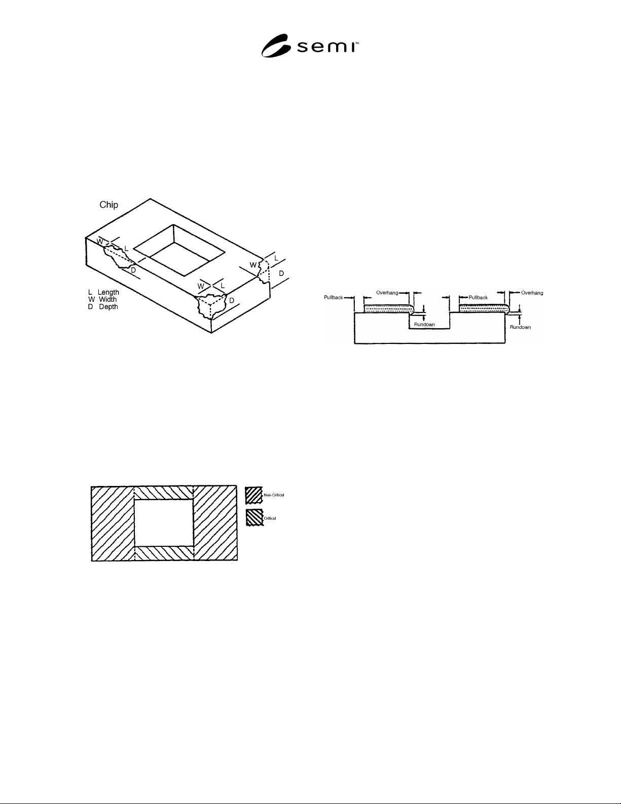
5.4 chip — A region of material missing from a
component (e.g., ceramic from a package, or solder
from a preform). The region does not progress
completely through the component and is formed after
the component is manufactured. Chip size is defined by
its length, width, and depth from a projection of the
design planform. Also called chipout (see Figure 1).
Figure 1
5.5 crack — A cleavage or fracture that extends to the
surface of a semiconductor package or solder
preform.The crack may or may not pass through the
entire thickness of the package or preform.
5.6 critical seal area — On a semiconductor package,
the area bounded by the shortest nominal design
distance from the largest cavity, usually the wire bond
cavity, to the edge of the package or ceramic layer
forming the seal area (see Figure 2).
Figure 2
Critical and Non-Critical Seal Area
5.7 fin — On a ceramic package or cap, a fine
feathery-edged projection of parent ceramic material on
the corner of the ceramic body.
5.8 foreign material — An adherent particle that is not
parent material of the component. Adherence means
that the particle cannot be removed by an air or nitrogen
blast at 20 psi.
5.9 glass flow — On a semiconductor package or cap,
the heating process which just removes all the screen
printing mesh marks in the sealing glass when viewed
at 10× magnification.
5.10 glass void — The absence of a sealing glass layer
from a designated area.
5.11 metallization void — The absence of a clad,
evaporated, plated, or screen-printed metal layer or
braze from a designated area.
5.12 non-critical seal area — On a semiconductor
package that uses a lid, cap, or cover to effect the seal,
the area of the sealing surface outside the critical
sealing area (see Figure 2).
5.13 overhang — On a semiconductor package, the
horizontal extension of the sealing glass past the
vertical wall of a cavity cut into the ceramic layer on
which the glass is printed (see Figure 3).
Figure 3
Glass Misalignment
5.14 peeling (flaking) — Any separation of a plated,
vacuum-deposited, or clad metal layer from the base
metal of a leadframe, pin heatsink, or seal ring, from an
underplate or from a refractory metal on a ceramic
package. Peeling exposes the underlying metal.
5.15 projection — On a semiconductor package
(plastic or ceramic) leadframe or preform, an irregularly
raised portion of a surface indigenous to the parent
material.
5.16 pullback — On a semiconductor package, the
linear distance between the edge of a cavity cut into a
ceramic layer and the first measurable glass or
metallization layer interface coated onto the top surface
of that layer. The total pullback may be the result of the
high-temperature processing required to manufacture
the package or to coat the surface. It may also be the
result of design considerations (see Figure 3).
5.17 rundown — On a semiconductor package, the
linear distance from the upper surface of a ceramic
cavity layer to the bottom point of the overhang into the
cavity, of a sealing glass or metallization layer that has
been screened onto that surface (see Figure 3).
5.18 seal area — On a semiconductor package, the
area designated for sealing a cover or lid to a cofired
ceramic package, to a cap to a cer-pack base.