semi合集-English.pdf - 第486页
SEMI E69-0298 © SEMI 1998, 2003 7 12.7.2 The reference po wer supply m ust be sufficiently rated for the DUT . In addition, t h e followi ng supply conditions and tolerances sh all apply: DC supply reference voltage ± 0.…
SEMI E69-0298 © SEMI 1998, 2003 6
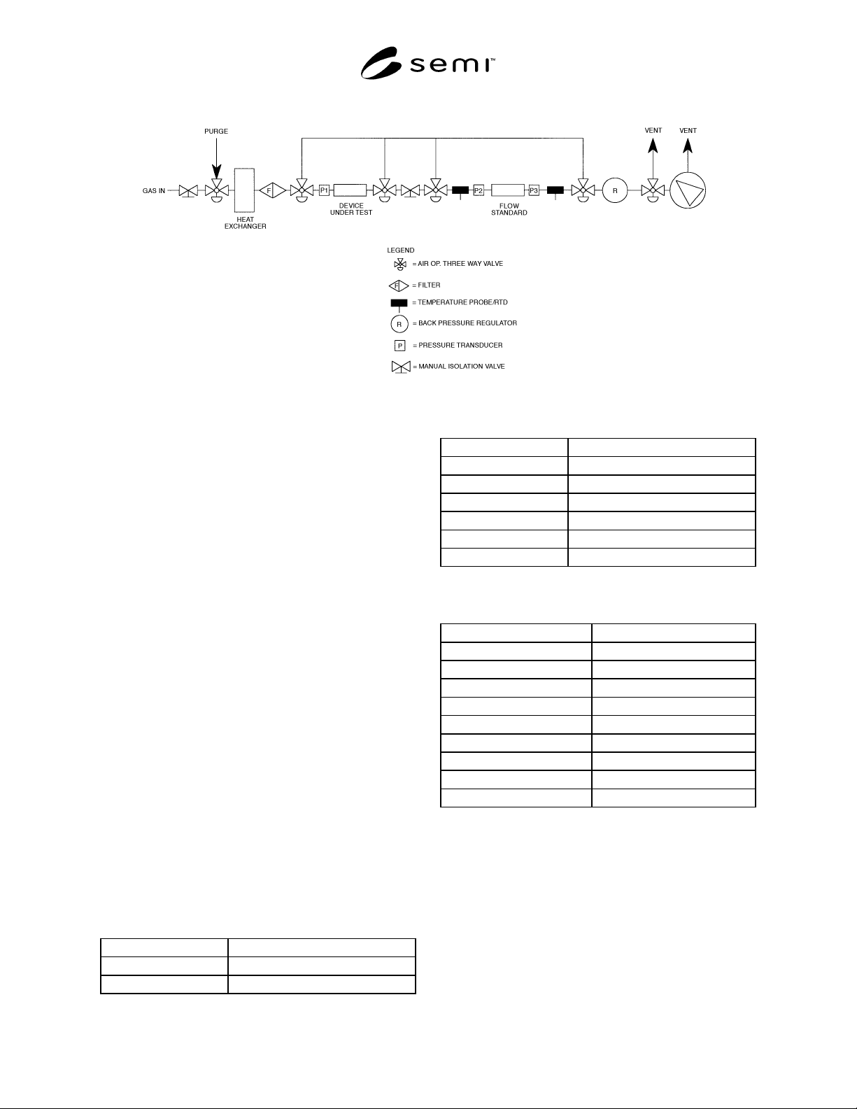
Figure 3
Mass Flow Controller Test Fixture
11 Calibration Standardization
11.1 All measurement devices must have valid
calibration certificates.
12 Conditioning
12.1 Place the MFC to be tested in the testing
environment. Apply power to the MFC for the 24 hours
prior to initiating warm-up as defined by the
manufacturer. The valve should be in its “off” position
(closed for an NC valve, open for an NO valve).
12.2 Following the conditioning period, install and
warm up the device according to manufacturer’s
specifications.
12.3 Purge the MFC with nitrogen or argon following
the warm up period.
12.4 Allow the test gas to flow through the DUT for a
minimum of 10 minutes at 100% of flow.
12.5 Apply a 100% full-scale setpoint to the DUT and
wait for the flow to stabilize for 10 seconds. Apply the
lower setpoint limit to the DUT and wait for the flow to
stabilize for 10 seconds. Repeat this cycle two more
times. This process exercises the device before
initiating the test.
12.6 Test Conditions
12.6.1 The reference operating conditions shall be as
follows if the downstream pressure is atmospheric:
Ambient temperature 23 ± 2°C
Gas temperature Same as actual ambient
Ambient pressure 101.3 kPa (+ 4.7 or − 15.3 kPa)
Gas pressure P
1
, Inlet 274 ± 34 kPa
Gas pressure P
3
, Outlet 101.3 kPa (+ 4.7 kPa or − 15.3 kPa)
Relative humidity 40% ± 10%, noncondensing
Magnetic field ≤ 50 µT
Electromagnetic field < 100 µV/m
Vibration < 0.5 m/s
Shock ≤ 3 g
12.6.2 The reference operating conditions shall be as
follows if the downstream pressure is at vacuum:
Ambient temperature 23 ± 2°C
Gas temperature Same as actual ambient
Ambient pressure 101.3 kPa (+ 4.7 or − 15.3 kPa)
Gas pressure P
1
, Inlet 172 ± 34 kPa
Gas pressure P
3
, Outlet < 0.13 kPa
Relative humidity 40% ± 10%, noncondensing
Magnetic field ≤ 50 µT
Electromagnetic field < 100 µV/m
Vibration < 0.5 m/s
Shock ≤ 3 g
12.7 Power Supply Conditions
12.7.1 The reference power supply conditions used
shall be the reference values specified by the
manufacturer. For those instances when a range of
values is specified rather than a reference value, the
midpoint of the range shall be taken to be the reference
value.
SEMI E69-0298 © SEMI 1998, 2003 7
12.7.2 The reference power supply must be sufficiently
rated for the DUT. In addition, the following supply
conditions and tolerances shall apply:
DC supply reference voltage ± 0.1% of operating voltage
Noise and ripple of DC supply ≤ 0.1% rms
13 Procedure
13.1 Zero Offset
13.1.1 Close the gas shut-off valve upstream of the
device under test and apply a 100% setpoint to the DUT
to equilibrate the pressure across the MFC. Wait for the
flow to stabilize at a value near zero, then close the
downstream shut-off valve. Deactivate the MFC’s
control valve (open for (NO) valves, closed for (NC)
valves), and disable the MFC to auto zero if an auto-
zero disable option is available. After the electrical
output signal has stabilized for at least three minutes,
record the MFC zero offset on Table 1. (Consult the
manufacturer’s specifications for the stabilization time
and report this time on Table 2.)
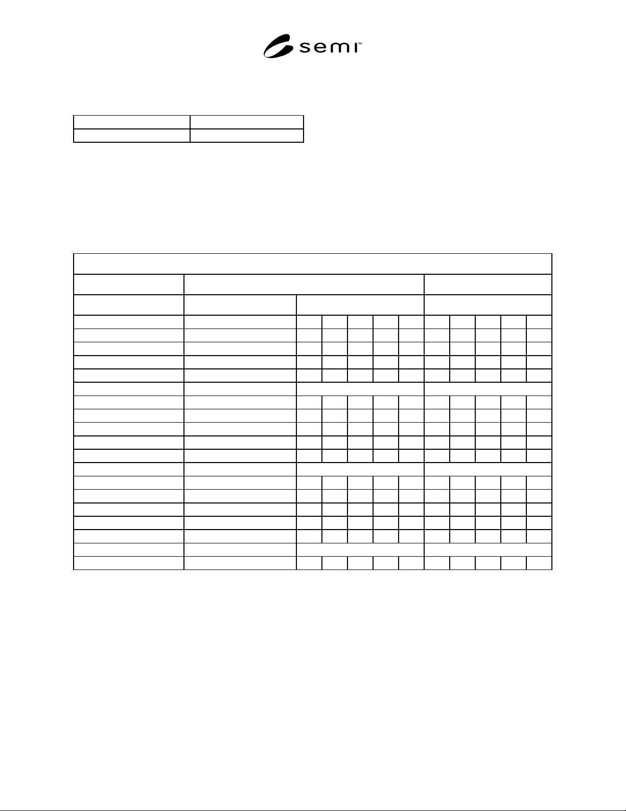
Table 1 Data Tabulation
Week #___________
D
ate_____________
_
Technician________________________
M
FC______________
_
Input % Set Point (sccm) Indicated Flow (sccm) Actual Flow (sccm)
0 0 0 0 0 0
50
100
50
10
5 Wait 10 minutes Record no data
10
50
100
50
10
5 Wait 10 minutes Record no data
10
50
100
50
10
5 Wait 10 minutes Record no data
10

SEMI E69-0298 © SEMI 1998, 2003 8
Table 2 Test Data Cover Sheet
MFC
Manufacturer__________ Model__________ Serial Number__________ Attitude__________
Nameplate Gas__________ Seal Type__________ Valve Seat Matl.__________ Full Scale Range__________
Environment
Ambient Temp. (°C)_________ Ambient Press. (kPa)________ Humidity (%)__________
Test Gas__________ Inlet Gas Pres. (kPa)_________ Outlet Gas Press.__________ Gas Temp. (°C)__________
Test Facility
Name__________ City/State__________ Telephone ( )__________ Fax ( )__________
Standard Used__________ Standard Accuracy__________ Facility Bias__________ Certification Date__________
Other Equipment__________ Accuracy__________ Certification Date__________
Other Equipment__________ Accuracy__________ Certification Date__________
Other Equipment__________ Accuracy__________ Certification Date__________
Other Equipment__________ Accuracy__________ Certification Date__________
Comments or Special Instructions:
Technician__________
Date__________
13.1.2 Use the cardinal setpoints and any other
setpoints of specific interest. These setpoints will be
used to determine the reproducibility of the MFC. The
setpoint increments should exceed the expected
deadband of the DUT.
13.1.3 At each setpoint under test, maintain the input
signal until the output of the DUT becomes stabilized at
its apparent final value. Observe and record the output
values in Table 1 for each input value.
13.1.4 Record five readings at each setpoint during
testing.
NOTE 2: If the data points show a trend in one direction,
either up or down, the DUT is not stable enough for the test to
proceed to the next setpoint. Record another five readings at
this setpoint. If the results continue to show a trend, repeat the
measurements at the previous setpoint. If the results are not
satisfactory at this setpoint, stop the test for this MFC. If the
results are not satisfactory, halt the test and verify the
performance of the testing apparatus.
13.1.5 At each point under test, maintain the input
signal until the output of the device under test becomes
stabilized at its apparent final value. Observe and
record the output values for each input value.
13.2 Reproducibility and Zero Drift Test
13.2.1 Apply a 50% setpoint to the MFC and record
data.
13.2.2 Move the setpoint to 100% and record data.
13.2.3 Move the setpoint to 50% and record data.
13.2.4 Move the setpoint to 10% and record data.
13.2.5 After recording data at 10%, apply a 5%
setpoint for 10 minutes, but do not record any data at
this setpoint.
13.2.6 Move the setpoint back up to 10% and record
data.