semi合集-English.pdf - 第4213页
SEMI F73-1102 © SEMI 2002 15 1 5 6 7 10 11 12 13 9 8 2 B D C E F H G J I K L M N O P Q S R TU 3 4 14 A 15 16 Figure A2-7 Scratch Counted in Grids H 3 -5, I5 and 6, J7 and 8, K8-10, L10 and 11, M12 and 13, N13-15, O15 and…
SEMI F73-1102 © SEMI 2002 14
1
5
6
7
10
11
12
13
9
8
2
B DC E
F
HG
JI KL
M
NOPQ SR TU
3
4
14
A
15
16
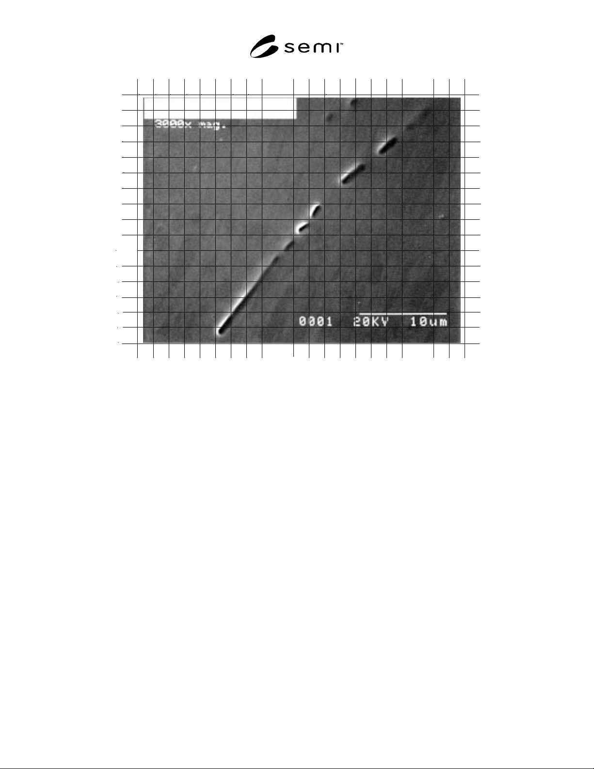
Figure A2-6
Long, Partially Continuous Stringer; the Inclusion that Formed this Stringer has been Electropolished Out.
All Grids Occupied by the Stringer Should be Counted, from F16 to S2. Also Pits at M2, N1 and O1.
SEMI F73-1102 © SEMI 2002 15
1
5
6
7
10
11
12
13
9
8
2
B DC E
F
HG
JI KL
M
NOPQ SR TU
3
4
14
A
15
16
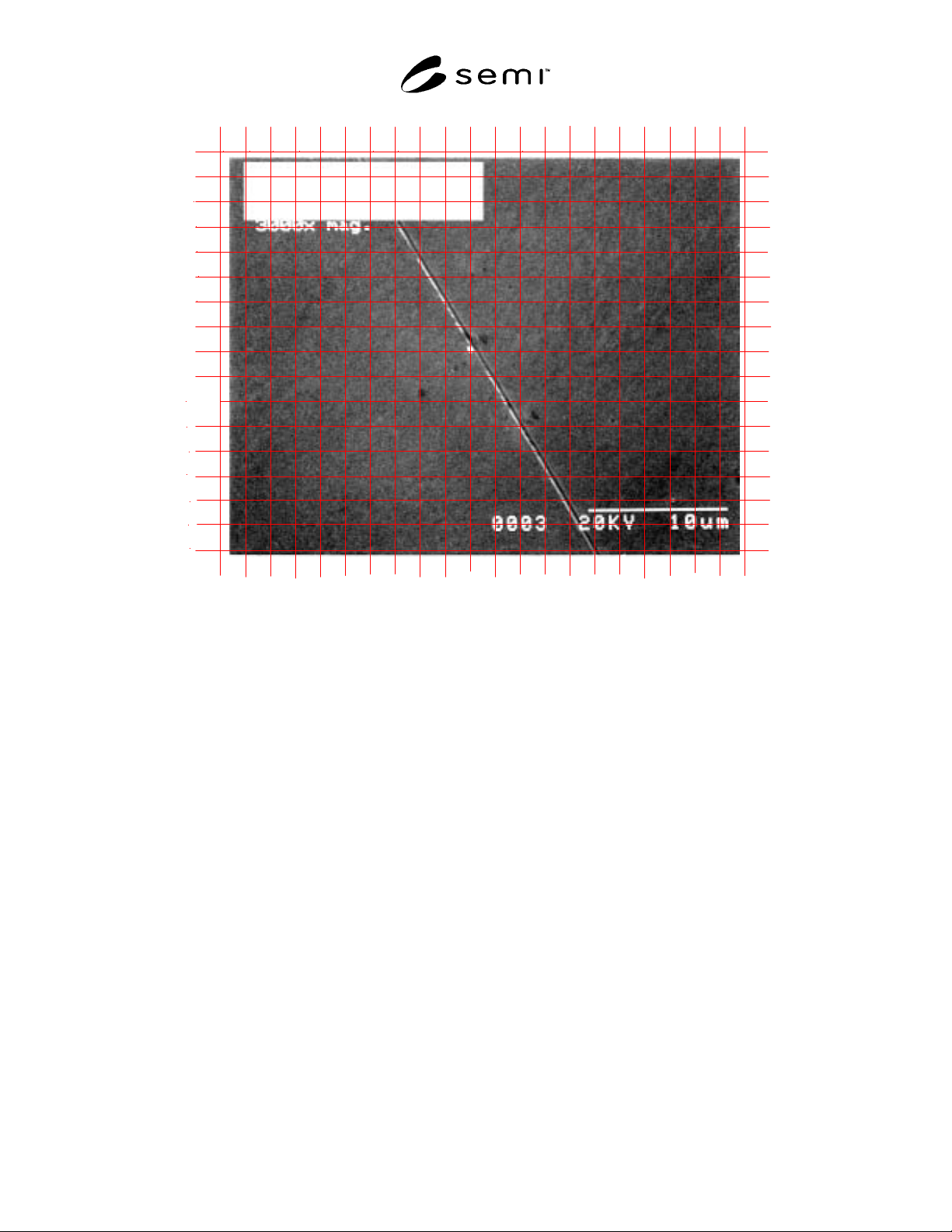
Figure A2-7
Scratch Counted in Grids H3-5, I5 and 6, J7 and 8, K8-10, L10 and 11, M12 and 13, N13-15, O15 and 16.
Pits Counted in Grids J9, H10, I10, M11.
NOTICE: SEMI makes no warranties or representations as to the suitability of the standards set forth herein for any
particular application. The determination of the suitability of the standard is solely the responsibility of the user.
Users are cautioned to refer to manufacturer' s instructions, product labels, product data sheets, and other relevant
literature, respecting any materials or equipment mentioned herein. These standards are subject to change without
notice.
By publication of this standard, Semiconductor Equipment and Materials International (SEMI) takes no position
respecting the validity of any patent rights or copyrights asserted in connection with any items mentioned in this
standard. Users of this standard are expressly advised that determination of any such patent rights or copyrights, and
the risk of infringement of such rights are entirely their own responsibility.
Copyright by SEMI® (Semiconductor Equipment and Materials
International), 3081 Zanker Road, San Jose, CA 95134. Reproduction o
f
the contents in whole or in part is forbidden without express written
consent of SEMI.

SEMI F74-1103 © SEMI 2002, 2003 1
SEMI F74-1103
TEST METHOD FOR THE PERFORMANCE AND EVALUATION OF
METAL SEAL DESIGNS FOR USE IN GAS DELIVERY SYSTEMS
This test method was technically approved by the Global Gases Committee and is the direct responsibility of
the North American Gases Committee. Current edition approved by the North American Regional Standards
Committee on September 16, 2003. Initially available at www.semi.org October 2003; to be published
November 2003. Originally published November 2002.
1 Purpose
1.1 This document is a test method for evaluating
metal seal designs use in gas delivery systems. It
covers both surface-mounted gas systems and
conventional metal face seal fitting systems.
2 Scope
2.1 The test methods apply to the connection seals used
in conventional tubing type gas systems and between
modules and components to the substrates used in
surface-mounted gas systems.
NOTICE: This standard does not purport to address
safety issues, if any, associated with its use. It is the
responsibility of the users of this standard to establish
appropriate safety and health practices and determine
the applicability of regulatory or other limitations prior
to use.
3 Limitations
3.1 This test method does not provide detailed
information sufficient for conducting the procedures. It
is the responsibility of the user to procure a copy of the
referenced test procedures from the issuing
organizations.
3.2 The test methods mentioned in this document are
destructive in some cases. Therefore, the sequence of
tests should be carefully planned with the
understanding that several specimens are required to
complete the battery of all applicable tests without
invalidating later tests. This requirement of several
specimens is in addition to the iteration normally
required under good statistical practices.
3.3 All components must meet quality requirements
(dimensional, sealing-surface finish, etc.), as
established and controlled by manufacturers prior to
testing.
3.4 Surface-mounted connection methods and system
design will affect exterior load testing (i.e., vibration,
shock, etc.).
3.5 Seals must be manufactured and packaged for
Class 100-type applications.
3.6 Care should be exercised in handling seals to
maintain manufacturer’s specifications.
4 Referenced Standards
4.1 SEMI Standards
SEMI E49 — Guide for Standard Performance,
Practices, and Sub-Assembly for High Purity Piping
Systems and Final Assembly for Semiconductor
Manufacturing Equipment
SEMI F1 — Specification for Leak Integrity of High-
Purity Gas Piping Systems and Components
4.2 ASME Standards
1
B31.3 — ASME Code for Process Piping
4.3 Military Standard
2
MIL-STD-810E — Environmental Test Methods and
Engineering Guidelines
4.4 Federal Standard
3
Federal Standard 209E — Airborne Particle Cleanliness
Classes in Cleanrooms and Clean Zones
4.5 ISO Standards
4
ISO 14644-1 — Cleanrooms and associated controlled
environments -- Part 1: Classification of air cleanliness
ISO 14644-2 — Cleanrooms and associated controlled
environments -- Part 2: Specifications for testing and
monitoring to prove continued compliance with ISO
14644-1
1 American Society of Mechanical Engineers, Three Park Avenue,
New York, NY 10016-5990, USA. Telephone: 800.843.2763
(U.S./Canada), 95.800.843.2763 (Mexico), 973.882.1167 (outside
North America), Website: www.asme.org
2 Available through the Naval Publications and Forms Center, 5801
Tabor Avenue, Philadelphia, PA 19120-5099, USA. Telephone:
215.697.3321
3 Federal Standard,, c/o U.S. Government Printing Office,
Washington DC 20402
4 International Organization for Standardization, ISO Central
Secretariat, 1, rue de Varembé, Case postale 56, CH-1211 Geneva 20,
Switzerland. Telephone: 41.22.749.01.11; Fax: 41.22.733.34.30,
Website: www.iso.ch