semi合集-English.pdf - 第4520页
SEMI D25-0600 E © SEMI 2000, 2003 3 6.2 Packi ng Box Dimensions — Figure 5 shows t he key dimensions a n d tolera nces of the packing box for the full box type . 6.2.1 Packi ng Box Loading and Unloading 6.2.1.1 Vertical …
SEMI D25-0600
E
© SEMI 2000, 2003 2
• Taking into consideration the head clearance when loading and unloading by forklift, as well as the height of
the shipping case, the maximum height of the load is approximately 2,000 mm. If more efficient loading can be
achieved, multiple boxes can be stacked.
4 Referenced Documents
4.1 SEMI Standards
SEMI D9 — Definitions for Flat Panel Display Substrates
SEMI D11 — Specification for Flat Panel Display Glass Substrate Cassettes
SEMI D24 — Specification for Glass Substrates Used to Manufacture Flat Panel Displays
4.2 JIS Documents
1
JIS D4002 — Internal Dimensions for Rear Body of Motor Trucks
JIS Z0604 — Wooden Flat Pallets
4.3 ISO Documents
2
ISO 668 — Series 1, Freight Container – Classification, Dimensions and Ratings
NOTE 1: As listed or revised, all documents cited shall be the latest publications of adopted standards.
5 Terminology
5.1 Size of exposed portion — The length of the glass substrate exposed from the packing box (full box type) when
the lid of the packing box is open.
6 Packing
6.1 Classification
6.1.1 Classification of packing is as follows:
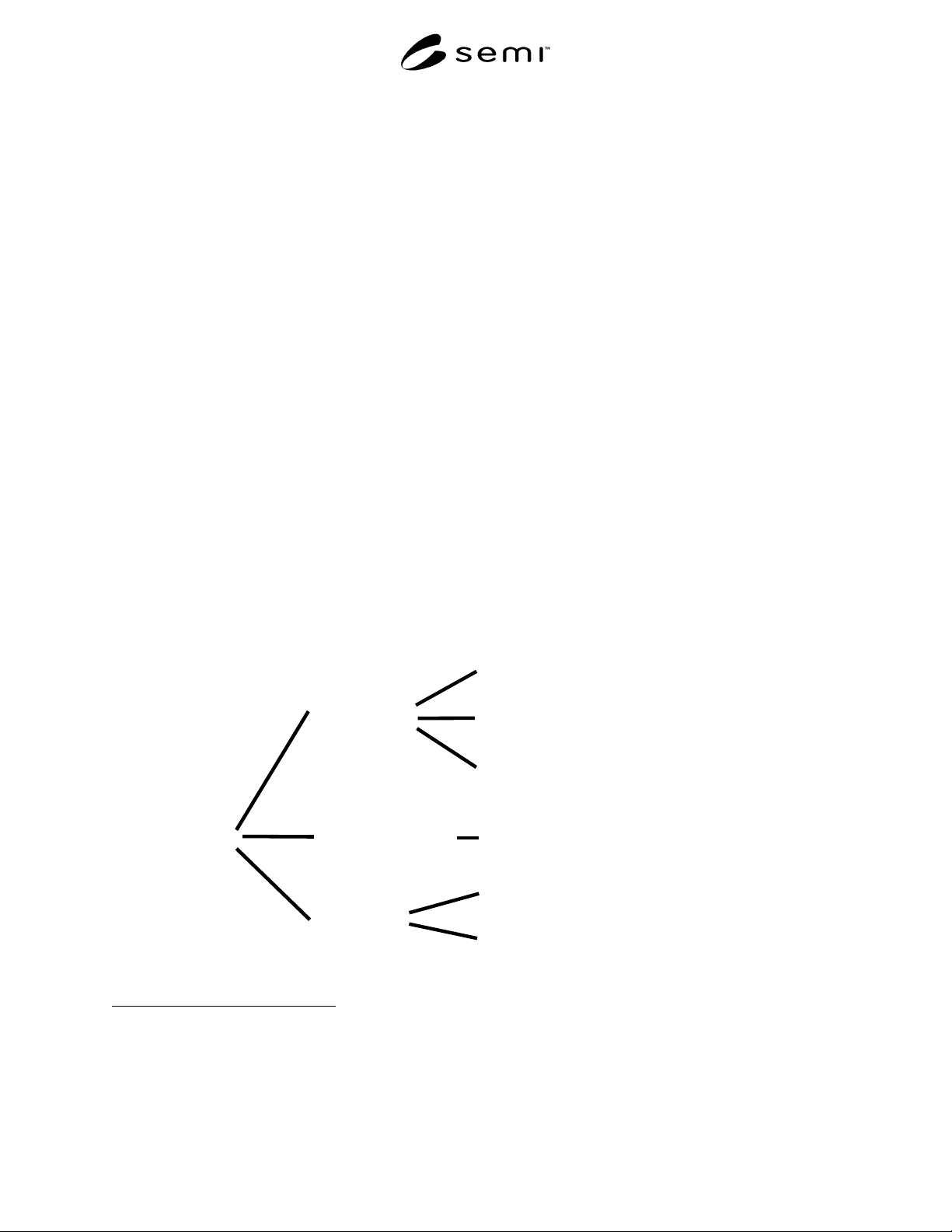
Packing
Separating type
Semi-separating type
Contact type
Full box type (Figure 2)
Full corner support type (Figure 3, left)
Double side supporter type (Figure 3, right)
Spacer type (Figure 4, top)
Interleaf paper type (Figure 4, down)
Interleaf film type
1 Japan Standards Association, 4-2-24, Minato-ku, Tokyo 107, Japan
2 ISO Central Secretariat, C.P. 56, CH-1211 Geneve 20, Switzerland
SEMI D25-0600
E
© SEMI 2000, 2003 3
6.2 Packing Box Dimensions — Figure 5 shows the key dimensions and tolerances of the packing box for the full
box type.
6.2.1 Packing Box Loading and Unloading
6.2.1.1 Vertical loading shall be used to load and
unload the glass substrates to and from the packing box
(see Figure 6).
6.2.1.2 Vertical loading requires a tall loader/unloader
because of the height of the loading direction. The
ceiling height of the room where the loading equipment
is installed has to be designed accordingly.
6.2.1.3 A suggested method for loading/unloading
substrates from the shipping case with an automatic
vertical loader/unloader is to tilt the box as shown in
Figure 7. Align the substrates on one side of the clear-
ance of the mizo and proceed with loading/unloading.
6.2.1.4 An alternative method for loading/unloading
would be to rotate the packing box 90°, as shown in
Figure 8.
6.2.1.5 Loading and unloading the substrates also can
be done manually without using an automatic
loader/unloader.
6.2.2 Packing Box Size
6.2.2.1 The shorter side of the substrate (side W, or the
800 mm side) as the vertical direction (direction z in
Figure 5) during shipping. This way, the size of the
substrate determines the inside measurements of the
packing box, H: 800 mm (direction z), W: 950 mm
(direction x).
6.2.2.2 The outside measurements of the packing box
shall be H: 980 mm × W: 1,200 mm × L: <
1100mm
(Figure 5). It is important to note that the height of 980
mm indicates that it is possible to stack up the packing
boxes, i.e. 980 mm × 2 = 1,960 mm, and still be less
than the possible maximum height (2,000 mm) of the
truck load.
6.2.2.3 The length of the packing box is determined by
the calculated product of the pitch size between the
substrates times the number of substrates stored in the
box. the length (L in Figure 5) of the packing box
cannot exceed 1,100 mm
6.2.3 Packing Box Lid
6.2.3.1 The packing box must prevent the substrates
from getting contaminated as well as to give pressure to
the substrates for securing them from both top and
bottom. The lid must securely seal and be able to latch
closed to the packing box by a lock. The latching
mechanism must allow easy automatic lock and unlock
as well.
6.2.3.2 The lid shall also have automatic and manual
opening/closing capability. The inside of the lid is
covered with a shock absorber that functions to secure
the glass substrates by pressing them from the top and
bottom.
6.2.4 Mizo Pitch and Capacity of Packing Boxes
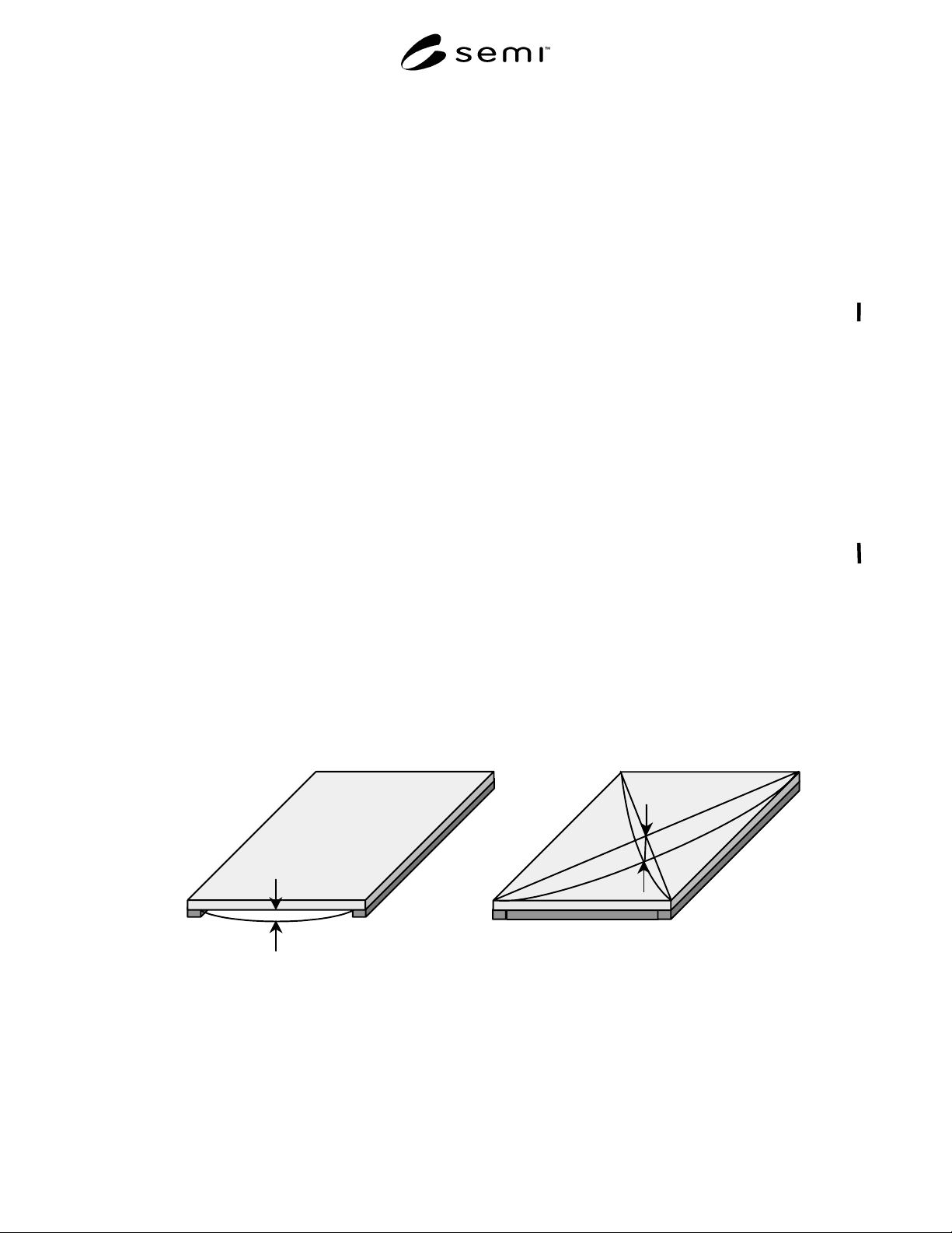
6.2.4.1 The sag, h4 = 20 mm will be for the substrates
of the size 800 × 950 × 0.7 mm as shown in Appendix
3, when a sudden turn, acceleration, or braking during
shipping forces a 1G acceleration against the substrates.
From this point of view, the pitch required here is a
little bit larger than 20 mm. However, since all the
substrates in the box are affected by the acceleration at
the same time and in the same direction, the distance
between the substrates will remain constant which
means the substrates should not touch each other.
6.2.4.2 The mizo pitch, must be standardized by each
shipping case supplier, but must range from a minimum
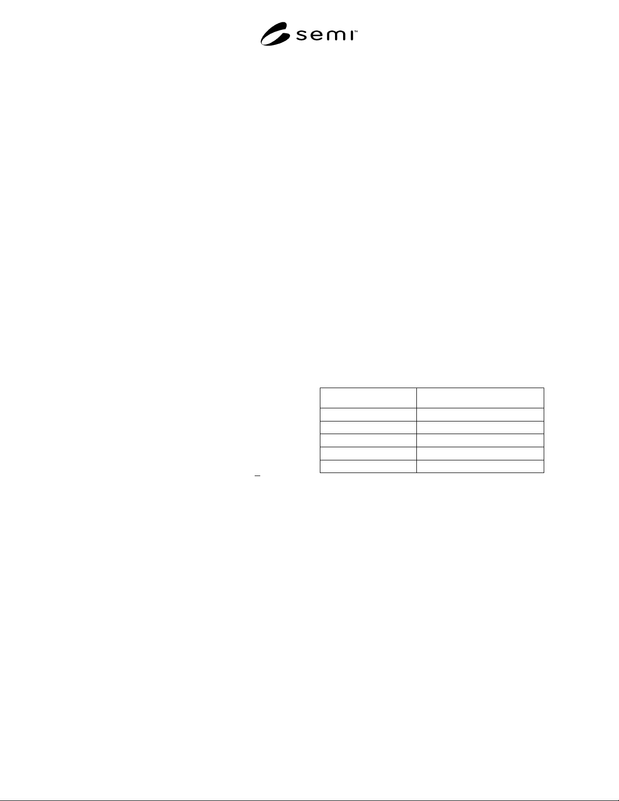
of 9 mm to a maximum of 22 mm ± 0.2 mm. Table 1
shows possible number of substrates per shipping case
at a given pitch.
Table 1 Pitch and Number of Substrates
Pitch (mm) Number of Substrates (pc)
22 40
18 50
15 60
11 80
9 100
6.2.4.3 The first mizo clearance (see Figure 9) is to be
more than 40.0 mm at the center of the groove. The
distance from the reference plane to the first mizo is the
sum of the first mizo clearance and the thickness of the
side of the box which is the reference plane, and its
allowance is ± 1.0 mm. The allowance of cumulative
pitch distance is less than ± 2.0 mm, and that of each
pitch is less than ± 1.0 mm.
6.2.4.4 Mizo clearance shall be designed to store the
glass substrate of a thickness ranging from 0.7 mm to
1.1 mm.
6.2.5 Size of Exposed Portion
6.2.5.1 In this document, the size of f1 in Figure 10 is
called “the size of the exposed portion” which is set as
f1 = 100 mm. Size h in Figure 10 is the shorter side of
the substrate at 800 mm. The size of f2 is 700 mm
which means one eighth of the whole substrate is
exposed.
SEMI D25-0600
E
© SEMI 2000, 2003 4
6.2.6 Reference Plane
6.2.6.1 The reference plane needs to be determined as
follows from three directions, x, y, and z in Figure 5 for
automatic transferring:
x: Both sides or center position
y: Both sides or center position
z: Bottom surface of the box (not the bottom of the
skid described later)
6.2.6.2 Specifically use the small area as a reference
surface in Figure 11. The detail of the position and size
of the reference surfaces shall be standardized to use a
compatible reference for two different design boxes.
Also the center line of substrate is automatically
defined by symmetrical location between substrate and
reference plane of case.
6.2.7 Transfer and Lift Method for Packing Boxes
6.2.7.1 It is expected that not only boxes containing
glass substrates but also empty boxes are fairly heavy.
At least, they probably cannot be carried by hand.
Therefore, it is assumed that whether the box contains
glass substrates or not and whether the box is in a
regular room or a clean room, it shall be lifted by a
forklift and transferred mechanically. To accommodate
a mechanical transfer and lift, skids must be installed at
the bottom of the box so that the forklift can insert its
tongues underneath the box (see Figure 5). The height
of the skids shall be standardized for each shipping case
supplier, but not exceed 150 mm.
6.2.7.2 Assuming lifting of the box and short distance,
transfer is done using a balancer; the packing box is
required to have handles, as shown in Figure 12, on the
sides of the box. The structure of the handles shall be
designed in such a way that it does not hinder the
reference plane.
6.2.8 Packing Box Strength
6.2.8.1 The weight of the contents of the box, with the
prescribed number of substrates, can be calculated from
the density of substrates. The packing box has to be
strong enough to bear that weight. Moreover, it has to
be strong enough to hold another full box on top of
itself.
6.2.8.2 Stacking three boxes with glass substrates is
prohibited. Therefore there is no need for the packing
box strength to hold two boxes on top of one box.
However, empty boxes may be stacked three high, but
the box has to be designed to bear the weight of two
empty boxes.
6.2.8.3 The handles shall be strong enough to hold the
weight when the box is filled with glass substrates as
well as a full box on top or two empty boxes on top.
6.2.9 Packing Box Material
6.2.9.1 Packing box material is not covered in this
document. Neither carcinogen nor de-gasification is
covered. For the purpose of cleaning, cleanliness, and
particle reduction, the material of the box has to be
washable and solvent-resistant. The addition of draining
holes is acceptable. Material must meet cleanliness,
mechanical strength, and durability in line with
specifications of this document.
h
Long Edge
2 Edge Support
W
L
4 Edge Support
h4
W
L
Figure 1
Sag