semi合集-English.pdf - 第2027页
SEMI E54.8-0305 © SEMI 1999, 2005 9 7.4.3 Assembly Objects and Local Link Objects whic h are ob jects embedded in the SAC Object is not expli citly mapped. 7.5 Attributes 7.5.1 General 7.5.1.1 All attributes are accessib…
SEMI E54.8-0305 © SEMI 1999, 2005 8
7.2 Object Model
7.2.1 The Object Model defined in the CDM is represented in the PROFIBUS NCS. Specifically, the DM and SAC
objects are mapped.
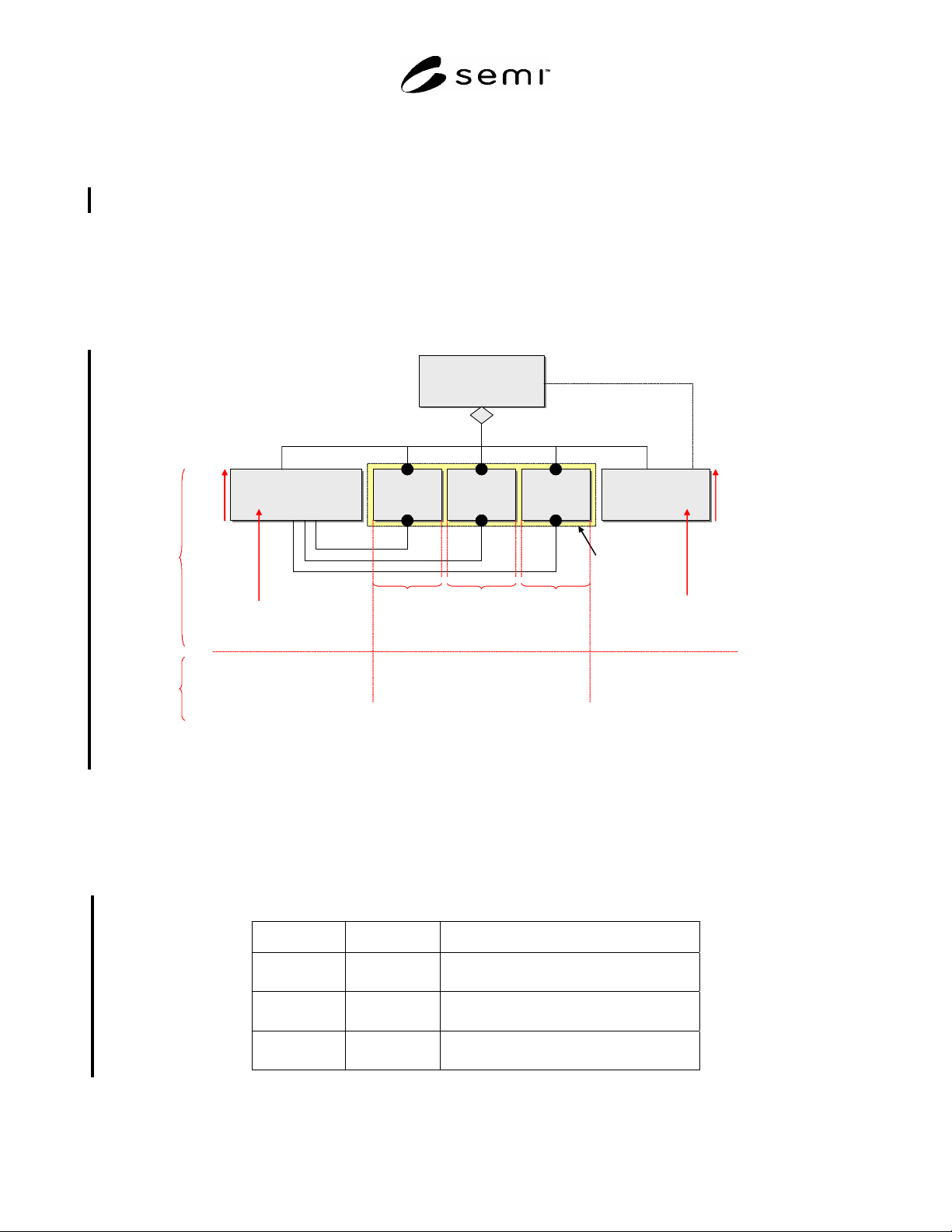
7.2.2 The CDM Objects are mapped to slots. These slots have a unique address space within the device. The
Application Objects associated with the SDM standards are mapped in PROFIBUS-DP Device Data Base
documents as defined above in the Device Profile/Device Data Base section. §9 specifies the mapping of SDM
Objects in PROFIBUS-DP.
7.3 Component Mapping Summary
7.3.1 Figure 2 provides a summary of the components of the CDM object model as they relate to the components of
PROFIBUS-DP.
Device
Device
Sensor/Actuator/
Controller Object
(SAC)
Sensor/Actuator/
Controller Object
(SAC)
Sensor
Object(s)
Sensor
Object(s)
Actuator
Object(s)
Actuator
Object(s)
Controller
Object(s)
Controller
Object(s)
Device Manager
Object
(DM)
Device Manager
Object
(DM)
is managed by
(Aggregation)
coordinates
m + n + p * 1
mn p
mn p
Active Element
Slot 0
Slot 0
1 Slot
per object,
starting with
Slot 1
1 Slot
per object,
starting with
Slot m+1
1 Slot
per object,
starting with
Slot m+n+1
Index
64
95
other Services
Cyclic
Services
Cyclic Data Structures will
be defined by Device Families
(Profiles) and via GSD
Figure 2
Component Mapping Summary
7.4 Objects
7.4.1 The required objects of the CDM are identified here. Additional objects that are contained in the SDM are
given identifiers in the Device Profile. §9 specifies additional mapping information.
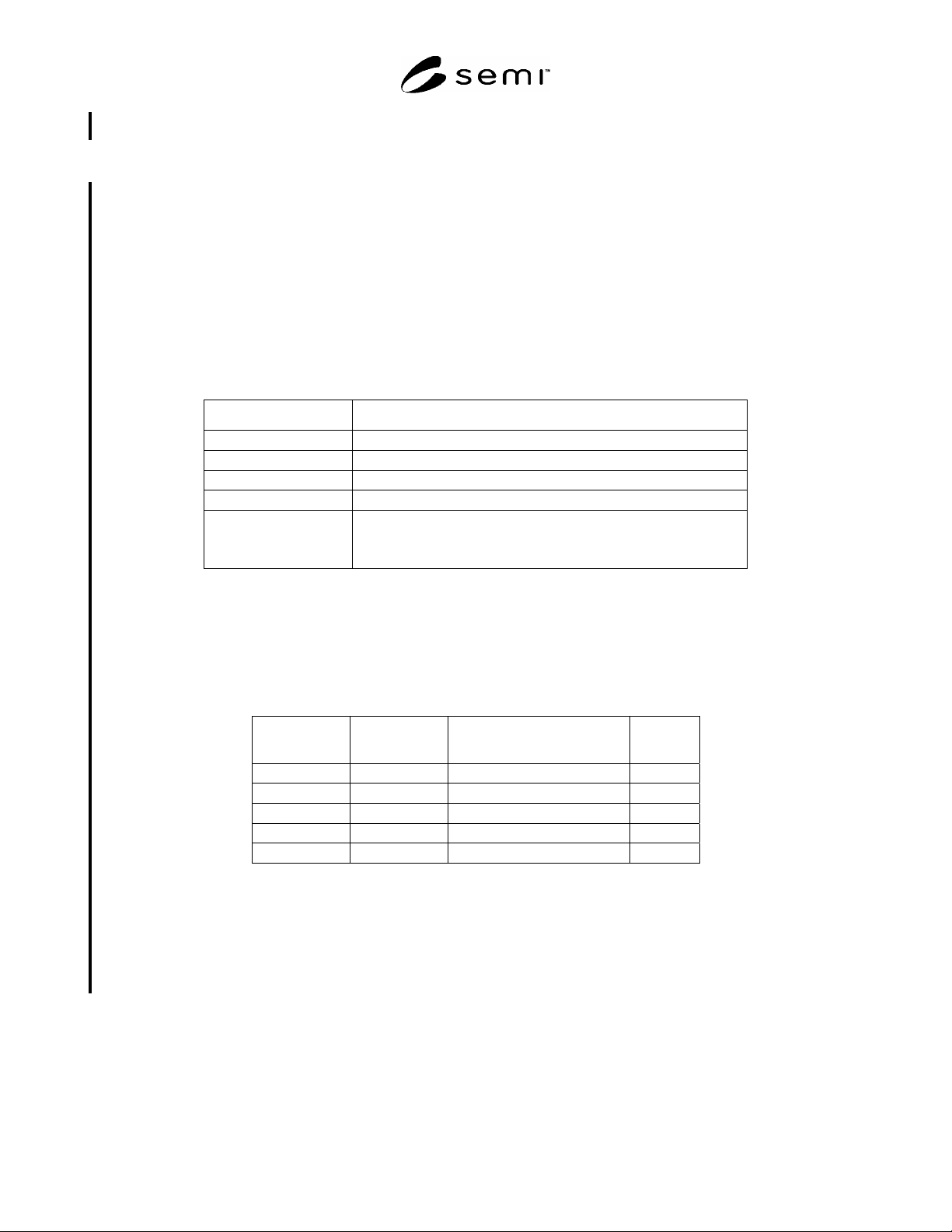
7.4.2 Table 3 lists the Object Identifiers specified for use in protocol messages. Slot numbers are the way for
addressing Objects within PROFIBUS-DP.
Table 3 Object Identifiers
Slot ID Index Object
0 IM0-17
96
DM Object
DM Control
0 64
65–95
SAC Control
SAC Object
1–n 32–254 Application Objects as specified
in §§ 7 and 9.
SEMI E54.8-0305 © SEMI 1999, 2005 9
7.4.3 Assembly Objects and Local Link Objects which are objects embedded in the SAC Object is not explicitly
mapped.
7.5 Attributes
7.5.1 General
7.5.1.1 All attributes are accessible via Get_Attribute and Set_Attribute services defined in the sections below.
Additionally, attributes are accessible via different PROFIBUS-DP defined methods which are mapped in this
document based on attribute type.
7.5.2 DM Attributes
7.5.2.1 All attributes are communicated with Read and Write Service and mapped to IM Blocks. Status attributes
are modeled additionally as Channel Diagnosis. See Table 18 for detailed mapping.
7.5.2.2 Table 4 shows the DM status attribute mapping to Diagnosis.
Table 4 Channel Diagnosis mapping of DM Status
Parameter Value
Identifier_Number = SlotID of the Object
Channel_Number 0 = Global
Channel Type 0 = unspecified
IO Type 0 = unspecified
Error Type 9 = Error with Bit0 - 6 set in Common Exception Detail 1
21 = Error Calibration set in Common Exception Detail Attribute 1
17 = Error with Bit set in Common Exception Detail 2
7.5.3 SAC Attributes
7.5.3.1 The attributes of SAC are mapped to Process data objects of PROFIBUS.
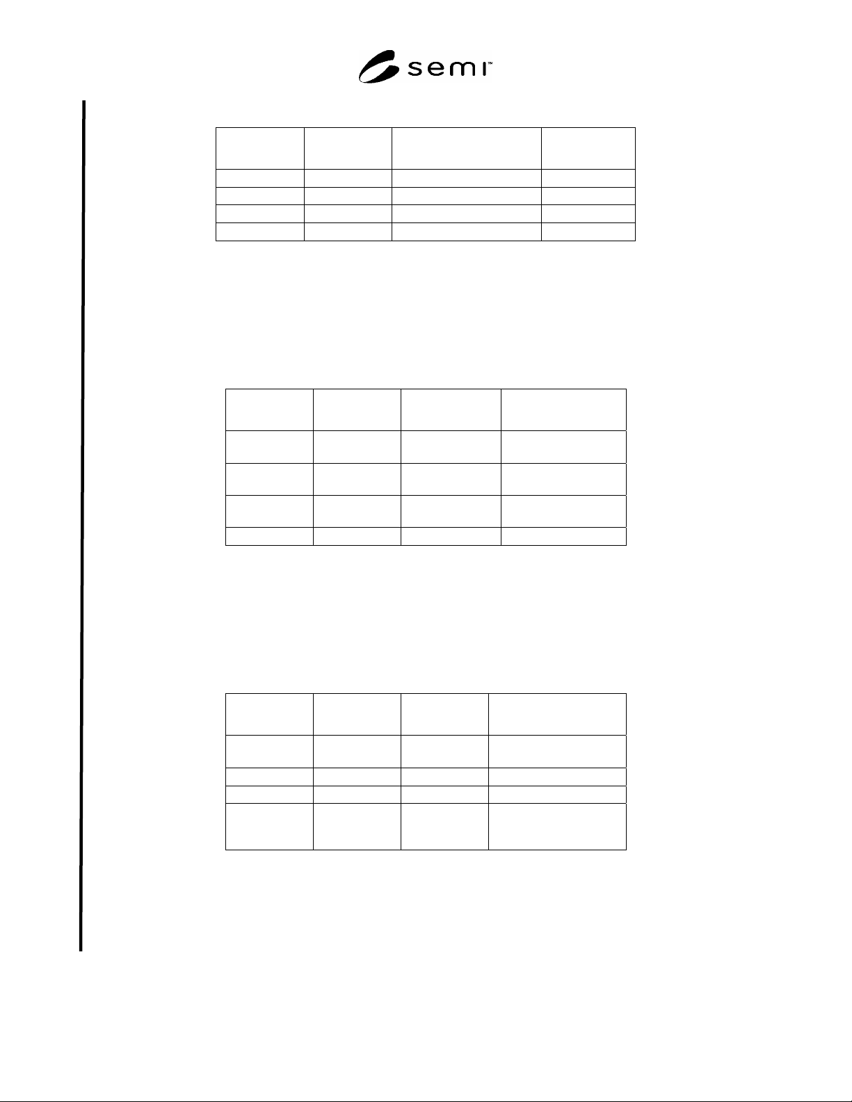
7.5.3.2 The Slot number used is 0. The index is the numeric value of the SAC Attribute identifier with an offset of
64 (see Table 5).
Table 5 SAC Object Attribute Identifiers
SEMI CDM
Attribute ID
PROFIBUS
Index
Attribute Detail
SacA1 65 Last Calibration Date
SacA2 66 Next Calibration Date
SacA3 67 Expiration Timer
SacA4 68 Expiration Warning Enable
SacA5 69 Run Hours
7.5.4 Active Element Attributes
7.5.4.1 The attributes of Active Elements are mapped to Process data objects of PROFIBUS. These attributes are
contained in any Sensor, Actuator and Controller Object.
7.5.4.2 The Slot number used is the instance number in the device. The index is the numeric value of the Active
Element Attribute identifier with an offset of 64 (see Table 6).
SEMI E54.8-0305 © SEMI 1999, 2005 10
Table 6 Active Element Object Attribute Identifiers
SEMI CDM
Attribute ID
PROFIBUS
Index
Attribute Detail/
A
lternative
Access Method
nA1 65 Name
nA2 66 Status
nA3 67 Alarm Enable
nA4 68 Warning Enable
7.5.5 Sensor Attributes
7.5.5.1 The attributes of Sensors are mapped to Process data objects of PROFIBUS. These attributes are contained
in any Sensor-AI, Sensor-EI and Sensor-BI Object.
7.5.5.2 The Slot number used is the instance number in the device. The index is the numeric value of the Sensor
Attribute identifier with an offset of 64 (see Table 7).
Table 7 Sensor Object Attribute Identifiers
SEMI CDM
Attribute ID
PROFIBUS
Index
Attribute Detail/Alternative
Access Method
nA16 80 Value Can be mapped as Input
Data Object
nA17 81 Report Inhibit
Time
nA18 82 Enable Report
Rate
nA19 83 Report Rate
7.5.6 Actuator Attributes
7.5.6.1 The attributes of Actuators are mapped to Process data objects of PROFIBUS. These attributes are
contained in any Actuator-AO, Actuator-EO and Actuator-BO Object.
7.5.6.2 The Slot number used is the instance number in the device. The index is the numeric value of the Actuator
Attribute identifier with an offset of 64 (see Table 8).
Table 8 Actuator Object Attribute Identifiers
SEMI CDM
Attribute ID
PROFIBUS
Index
Attribute Detail/Alternative Access
Method
nA16 80 Setting Can be mapped as Output
Data Object
nA17 81 Safe State
nA18 82 Watch Rate
nA19 83 Watch Dog The value of this variable
reflects the WD_Factor
parameter of PROFIBUS
7.5.7 Controller Attributes
7.5.7.1 The attributes of Controllers are mapped to Process data objects of PROFIBUS.
7.5.7.2 The Slot number used is the instance number in the device. The index is the numeric value of the Controller
Attribute identifier with an offset of 64 (see Table 9).