semi合集-English.pdf - 第6140页
SEMI G26-1296 E © SEMI 2002 4 6.6.2 Instrument Cond itions Typical operating conditions are: Excitation source 27 MHz plasma Carrier gas 99.999% Argon Sample flow 1 ml/min Power output 1000 watts Plasma temperature 8000°…

SEMI G29-1296
E
© SEMI 1986, 2002 3
6.5.3 Apparatus
6.5.3.1 Ion chromatograph (Dionex or equivalent). The
chromatograph shall be equipped with an injection
valve, a 50–100 µ l sample loop, and shall be set up with
the following:
1. Guard Column
2. Separator Column
3. Chemical Suppressor Device
4. Conductivity Detector
6.5.4 Reagents
6.5.4.1 Water Purity — Water used in the preparation
of eluents, standards, and sample extraction shall
conform to ASTM D 1193.
6.5.4.2 Reagent Purity — Reagent grade chemicals
should be used in all tests.
6.5.4.3 Eluent/Regenerant Solutions — Should be
prepared in accordance with instrument manufacturer’s
instructions recommended for each column set.
6.5.4.4 Stock Solutions — Stock solutions (1 ml - 1 mg
- 1 ppm ion of interest) should be prepared according to
accepted practice, and as described in the instrument
manufacturer’s instructions.
6.5.4.5 Calibration Standards — Prepare a blank and
at least three (3) different calibration solutions
containing combination of anion/cations. These
solutions must be prepared in volumeric flasks (see
Table 1).
6.5.4.5.1 Prepare a standard solution I by diluting the
volume of each anion/cation stock solution as specified
in Table 1 together with 1 litre of water.
6.5.4.5.2 Prepare a standard solution II by diluting 20
ml of standard solution II to 100 ml with water (see
Table 1).
NOTE 6: If the concentrations of the sample ions are known,
or estimated, the concentration of calibration standard
solutions may be varied to better approximate or bracket
concentration range of interest.
6.5.5 Calibration
6.5.5.1 Analyze the blank and each of the prepared
calibration solutions described in Section 6.5.4.5.
6.5.5.2 Prepare analytical curves for each anion/cation
of interest by plotting on linear graph paper peak height
or peak area versus nominal concentrations of the
anion/cation calibration standard.
NOTE 7: Each analytical curve should be established using
only one (1) scale setting.
6.5.6 Procedure
6.5.6.1 Set-up the ion chromatograph according to the
manufacturer’s instructions.
NOTE 8: The range setting required for the analysis will
depend on the concentration of ions in the sample and should
be chosen accordingly. For these types of samples, operating
range from 30 to 30µ S/cm, full scale is most frqurntly used.
6.5.6.2 Equilibriate the system by pumping eluent
through the analytical system until a stable baseline is
obtained (approximately twenty (20) minutes).
6.5.6.3 Filter samples through a pre-washed 0.22 µ m
filter prior to analysis.
NOTE 9: Several types of syringe-tip filters are available
(Millipore or equivalent).
6.5.6.4 Load 2–3 ml of sample into the injection part
using a syringe. Inject the sample into the eluent stream
and record the ion chromatogram.
6.5.7 Calculations
6.5.7.1 Refer to the peak height or area for the
anions/cations of interest to the appropriate analytical
curves to determine the anion concentration.
6.6 Inductivity Coupled Argon Plasma
Spectrometry/ICP
6.6.1 Method Principle — Inductivity coupled Argon
Plasma (ICP) uses high frequency Argon Plasma to
excite sample constituents to 8000° K. Because the
plasma ionizes most atomic species, background
interferences are vastly reduced and linear response
over several orders of magnitude can be observed for
most elements. The sample extract is aspirated into the
plasma by means of a high purity argon carrier gas. The
resulting emissions are directed into the spectrometer
and signal strengths are read by photomultiplier tubes
placed at emission points in a focal curve. A computer
is used to scan each elemental channel many times a
second, and this output is sent to a printer in numerical
form. The cycle or time of analysis is usually about
seven (7) seconds. With this instrument, very little of
the extracted sample is consumed.
SEMI G26-1296
E
© SEMI 2002 4
6.6.2 Instrument Conditions
Typical operating conditions are:
Excitation source 27 MHz plasma
Carrier gas 99.999% Argon
Sample flow 1 ml/min
Power output 1000 watts
Plasma temperature 8000° K
Slit width of Spectrometer 30 µ m
6.6.3 Measurement of Sodium, Potassium, and Antimony — A standard solution of ten (10) ppm of sodium,
potassium, and antimony should be prepared and cycled through the ICP instrument. The blank extract sample and
the unknown molding compound extracts are then run through the ICP. The values obtained for sample are corrected
by subtracting values obtained for the blank. With the ICP, sodium, potassium, and antimony can be analyzed with
sensitivities to the ten (10) PPB levels. Any additional elements present may be obtained on the same cycle with no
additional preparation.
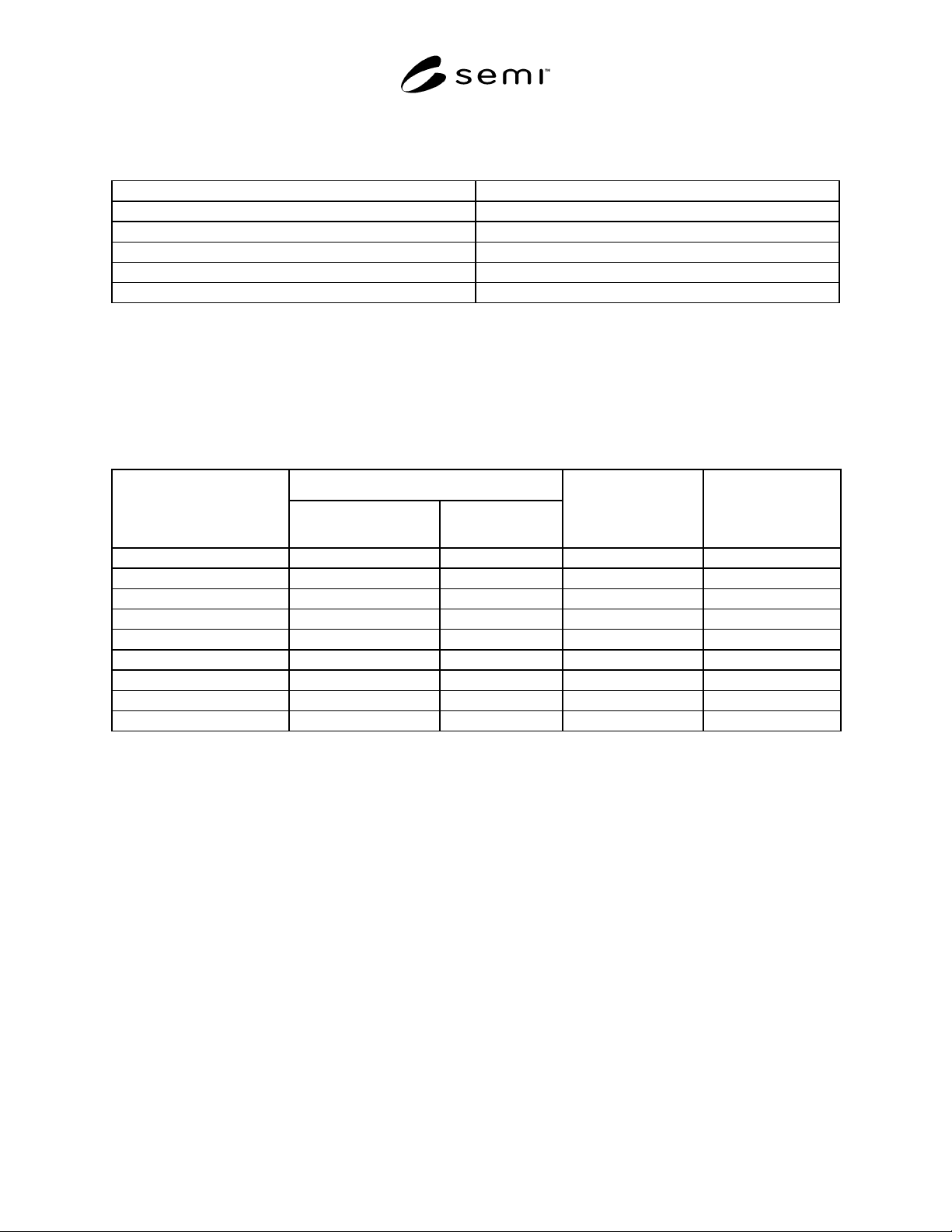
Table 1 Preparation of Standard Solutions for Instrument Calibration
Standard Solution
Anion
ml of Stock Soln. Diluted
to 1000 ml
Anion Conc. mg/1
Standard Solution II
Standard Solution III
Chloride (Cl) 5 5 1 0.2
Phosphate (HPO
4
2-
) 25 25 5 1.0
Bromide (Br
-
) 10 10 2 0.4
Nitrate (NO
3
30 30 6 1.2
Sulfate (SO
4
2-
) 25 25 5 1.0
Cation
Sodium (NA
+
) 5 5 1 0.2
Ammonium (NH
4
+
) 5 5 1 0.2
Potassium (K
+
) 10 10 2 0.4
NOTICE: SEMI makes no warranties or representations as to the suitability of the standards set forth herein for
any particular application. The determination of the suitability of the standard is solely the responsibility of the user.
Users are cautioned to refer to manufacturer’s instructions, product labels, product data sheets, and other relevant
literature respecting any materials mentioned herein. These standards are subject to change without notice.
The user’s attention is called to the possibility that compliance with this standard may require use of copyrighted
material or of an invention covered by patent rights. By publication of this standard, SEMI takes no position
respecting the validity of any patent rights or copyrights asserted in connection with any item mentioned in this
standard. Users of this standard are expressly advised that determination of any such patent rights or copyrights, and
the risk of infringement of such rights, are entirely their own responsibility.
Copyright by SEMI® (Semiconductor Equipment and Materials
International), 3081 Zanker Road, San Jose, CA 95134. Reproduction o
f
the contents in whole or in part is forbidden without express written
consent of SEMI.

SEMI G30-88 © SEMI 1986, 19881
SEMI G30-88
TEST METHOD FOR JUNCTION-TO-CASE THERMAL RESISTANCE
MEASUREMENTS OF CERAMIC PACKAGES
1 Purpose
The purpose of this test is to determine the thermal
resistance of ceramic packages using thermal test chips.
This test method deals only with junction-to-case or
mounting surface measurements of thermal resistance
and limits itself to heat sink and fluid bath testing
environments. Following the guidelines outlined in this
test method, junction-to-case thermal resistance
measurements of ceramic packages using the heat sink
and fluid bath methods should give the same results
only under certain limited conditions (i.e., under
conditions that approximate unidirectional heat flow
through the chip and substrate to the preferred heat
removal surface). If discrepancies occur, the heat sink
mounting technique shall be considered as the referee
test method. The heat sink mounting method for
measuring junction-to-case thermal resistance will be a
conservative measure of the package’s ability to
transfer heat to the ambient environment because heat
sinking is provided only on one side of the package,
whereas the fluid bath mounting method has the
potential for equally cooling both sides of the package.
1.1 Definitions — The following d efinitions and
symbols shall apply for the purpose of this test:
a. case temperature, T
C
, in degrees Celsius. The case
temperature is the temperature at a specified
accessible reference point on the package in which
the microelectronic chip is mounted.
b. mounting surface temperature, T
M
, in degrees
Celsius. The mounting surface temperature is the
temperature of a specified point at the device-heat
sink mounting interface (or primary heat removal
surface).
c. junction temperature, T
J
, in degrees Celsius. The
term is used to denote the temperature of the
semiconductor junction in the microcircuit in which
the major part of the heat is generated. For purposes
of this test, the measured junction temperature is
only indicative of the temperature in the immediate
vicinity of the element used to sense the
temperature.
d. power dissipation, P
H
, in watts, is the heating power
applied to the device causing a junction-to-reference
point temperature difference.
e. thermal resistance, junction-to-specified reference
point, R
ΘJR
, in degrees Celsius/watt. The thermal
resistance of the microcircuit is the temperature
difference from the junction to some reference point
on the package divided by the power dissipation P
H
.
f. temperature-sensitive parameter, TSP, is the
temperature-dependent electrical characteristic of
the junction under test which can be calibrated with
respect to temperature and subsequently used to
detect the junction temperature of interest.
2 Apparatus
2.1 The apparatus required for the se tests shall include
the following as applicable to the specified test
procedures.
a. Thermocouple material shall be copper-constantan
(type T) or equivalent, for the temperature range
-100 to +300°C. The wire size shall be no larger
than AWG size 30. The junction of the
thermocouple shall be welded to form a bead rather
than soldered or twisted. The accuracy of the
thermocouple and associated measuring system
shall be ± 0.5°C.
b. Suitable electrical equipment as required to provide
controlled levels of conditioning power and to make
the specified measurements. The instrument used to
electrically measure the temperature-sensitive
parameter shall be capable of resolving a voltage
change of 0.5 mV.
c. Controlled temperature chamber, fluid bath, or heat
sink capable of maintaining the specified reference
point temperature to within ± 0.5°C of the preset
(measured) value. Typical temperature-controlled
heat sink and fluid bath assemblies are presented for
illustrative purposes only.
2.2 Heat Sink Assembly — A typical heat sink
assembly for mounting the microelectronic device
under test is shown in Figure 1. The primary heat sink
is water cooled using a temperature-controlled fluid
circulator bath. An adapter socket/heat sink is fastened
to the heat removal surface of the primary heat sink,
and has a special geometry to handle specific size
packages (e.g., flat packs, dual-in-line packages, chip
carriers). This adapter provides a repeatable and