semi合集-English.pdf - 第1352页
SEMI E30-1103 © SEMI 1992, 2003 26 Thus, UPPERDB and LOWERDB as a pair define a limit. LOWERDB — A variable limit attribute that defines th e lower boundary of the deadband of a lim it. 18 The value applies to a single l…
SEMI E30-1103 © SEMI 1992, 2003
25
4.2.3.5 Scenario
Host Initiates Trace Report:
COMMENT HOST EQUIPMENT COMMENT
Trace Data initialization
requested S2,F23-->
<--S2,F24 Acknowledge, trace initiated
[DO] TOTSMP REPGSZ times
[DO] REPGSZ many times: collect
SVID
1
,...SVID
n
data, delay
time by DSPER.
[END_DO]
<--S6,F1 Send SV
1
,...SV
n
Acknowledge receipt S6,F2-->
[END_DO]
Optional:
Request trace termination prior to
completion (TOTSMP = 0) S2,F23-->
<--S2,F24 Acknowledge premature termination
4.2.4 Limits Monitoring — This capability relates to the
monitoring of selected equipment variables and has
three primary aspects:
— Defines a standard set of monitoring zones and
limits.
— Provides for reporting to the host when selected
equipment variables transition between monitoring
zones.
— Empowers the host to modify the values of the
variable limit attributes for these same selected
equipment variables.
4.2.4.1 Purpose — The limits monitoring capability
provides the host a means of monitoring equipment
conditions by a flexible, efficient, and asynchronous
method which is consistent across equipment. It
eliminates the need for constant polling of equipment
by the host for current status values. Further, this
capability allows the host to implement changes in the
monitoring range as needed. This capability has
application to both production operation and
diagnostic/testing scenarios, and it also has applicability
to statistical process control.
4.2.4.2 Definitions
LimitVariable — DVVAL containing the VID of a
specific equipment variable for which a zone transition
collection event has been generated.
EventLimit — DVVAL containing the LIMITID of the
limit crossed by LimitVariable.
TransitionType — DVVAL which defines the direction
of the zone transition which has occurred: 0 = transition
from lower to upper zone, 1 = transition from upper to
lower zone.
Limit — Used in this section to represent the set of
variable limit attributes that completely describe a
variable monitoring “barrier.” The attributes include
VID, Units, UPPERDB, LOWERDB, LIMITMAX, and
LIMITMIN. In some contexts it may be interpreted
more narrowly as the combination of UPPERDB and
LOWERDB.
LIMITID
n
— Refers to the identifier of a specific limit
(as defined by UPPERDB and LOWERDB) among the
set of limits for a monitored equipment variable.
LIMITIDs are consecutively numbered, beginning at
one through the number of limits possible (seven
minimum).
Monitoring Zone — A subset of the possible range of
values for a variable of interest to the host. A single
limit divides the range into two zones. Multiple limits
may be combined to divide the range even further.
Zone Transition — The movement of a variable value
from one monitoring zone to another. This transition is
a collection event and has a corresponding CEID.
Deadband — An overlap of two zones implemented to
prevent constant zone transitions by a variable sitting
on or near a limit (i.e., “chattering”).
UPPERDB — A variable limit attribute that defines the
upper boundary of the deadband of a limit.
18
The value
applies to a single limit (LIMITID) for a specified VID.
18 The format and units must be the same as the format of the
variable being monitored.
SEMI E30-1103 © SEMI 1992, 2003
26
Thus, UPPERDB and LOWERDB as a pair define a
limit.
LOWERDB — A variable limit attribute that defines the
lower boundary of the deadband of a limit.
18
The value
applies to a single limit (LIMITID) for a specified VID.
Thus, UPPERDB and LOWERDB as a pair define a
limit.
UPPER ZONE — The range of values lying above a
limit.
LOWERZONE — The range of values lying below a
limit.
LIMITMAX — The maximum value for any limits of a
specific equipment variable. This value is set by the
equipment manufacturer and typically coincides with
the maximum value allowed for the monitored variable.
LIMITMIN — The minimum value for any limits of a
specific equipment variable.
19
This value is set by the
equipment manufacturer and typically coincides with
the minimum value allowed for the monitored variable.
Undefined — When used in reference to variable limits,
it indicates that monitoring/reporting of zone transitions
involving that particular limit are disabled.
4.2.4.3 Description — The limits monitoring capability
provides the host with a minimum of seven
configurable limits or barriers that may be applied to
selected equipment status variables (SV’s) of the types
floating point, integer, and boolean. When one of these
barriers is crossed, a collection event is generated to
alert the host to a change in monitoring zone or state of
the monitored variable. These seven limits may be
combined in a variety of ways to match the needs of the
host system.
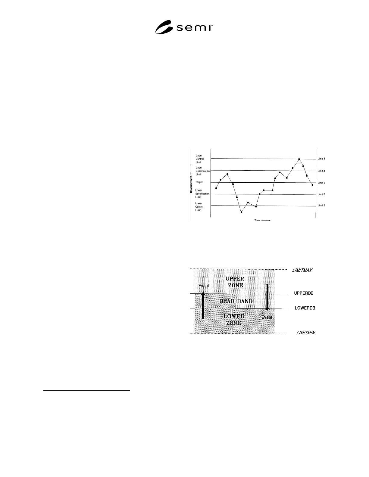
19
An illustration of a combination of five
of the limits to provide one type of variable monitoring
is shown in Figure 4.2.1.
20
This section describes the
key aspects of limits monitoring. Detailed
implementation examples of limits monitoring are
provided as Application Note A.7.
NOTE 6: While the SEMI E5 standard allows SV’s to be lists,
such variable lists are not allowed under this capability.
4.2.4.3.1 Monitoring Limit Characteristics — A limit
is defined by a set of attributes that include the variable
(VID) to which the limit corresponds, the units of that
variable, the maximum and minimum possible values of
19 Note that while at least seven limits per variable are available from
the equipment, the host need not use all seven.
20 This illustration shows the reading which might be available to the
equipment, not the limit excursions reported to the host. Reporting is
covered later in the section.
the limit (LIMITMAX and LIMITMIN) and the
specific borders of the limit (UPPERDB and
LOWERDB). See Figure 4.2.2. There is a limitation to
the values of UPPERDB and LOWERDB which may
be stated as:
LIMITMAX≥UPPERDB≥LOWERDB≥LIMITMIN
A limit divides the possible range of variable values
into two parts, the upper zone and the lower zone. At
any time, the monitored variable is considered to be in
one and only one of these zones. However, as Figure
4.2.2 shows, these two zones have an area of overlap.
This is called the deadband.
Figure 4.2.1
Limit Combination Illustration: Control
Application
Figure 4.2.2
Elements of One Limit
The deadband is a key concept of limits monitoring,
especially for floating point variables. Its purpose is to
prevent a phenomenon known as chattering — the
repeated changing of zones due to small, rapid
fluctuations in variable value while near the zone
boundary. In practice, the value of a variable must
reach the opposite boundary of the deadband before a
zone transition can occur. Thus, if a variable’s value
SEMI E30-1103 © SEMI 1992, 2003
27
reaches the UPPERDB and transitions into the upper
zone, it will not return to the lower zone until it falls
back to the LOWERDB. The difference between
UPPERDB and LOWERDB should always be greater
than the typical amplitude of those fluctuations deemed
to be insignificant. In some cases, the width of the
deadband may set to zero (i.e., UPPERDB =
LOWERDB). At first glance, this would seem to make
indeterminate the current zone when an integer value
sits on the limit. This is not the case, however, when
movement of the value is considered. To illustrate, an
example is given, assuming that UPPERDB =
LOWERDB = 100. The list shows consecutive readings
of the variable and the resultant zone:
99 Lower Zone (Initial Reading)
101 Upper Zone (Zone Transition)
100 Lower Zone (Zone Transition)
100 Lower Zone
99 Lower Zone
100 Upper Zone (Zone Transition)
Transition from one zone into another generates a
collection event, as might be reported via S6,F11. The
host has the option of receiving notification by enabling
event reporting for the event. For each variable that has
monitoring capability, one CEID is reserved to indicate
zone transitions for that variable. To aid in the
determination of the nature of a transition event, three
DVVAL’s have been defined:
LimitVariable — The VID of the monitored variable to
which the collection event refers.
EventLimit — Contains the LIMITID of the limit
reached or crossed by LimitVariable.
TransitionType — Defines the direction of the zone
transition which has occurred: 0 = transition from lower
to upper zone, 1 = transition from upper to lower zone.
Sampling frequency is an important element of limits
monitoring and should be considered during equipment
specification. If changes in variable value are relatively
fast compared to sampling frequency, it is possible for
some zone transitions to be missed or for multiple zone
transitions to occur between readings. Since it is
possible for zone transitions to occur “simultaneously”
or for limits to be identically defined, the DVVAL
EventLimit has been defined to allow for a list of
multiple zone transitions of a variable to be reported
with a single collection event.
It also should be emphasized that a single CEID is used
to report transitions in both directions across a limit.
Thus, reporting for one direction but not the other
cannot be configured.
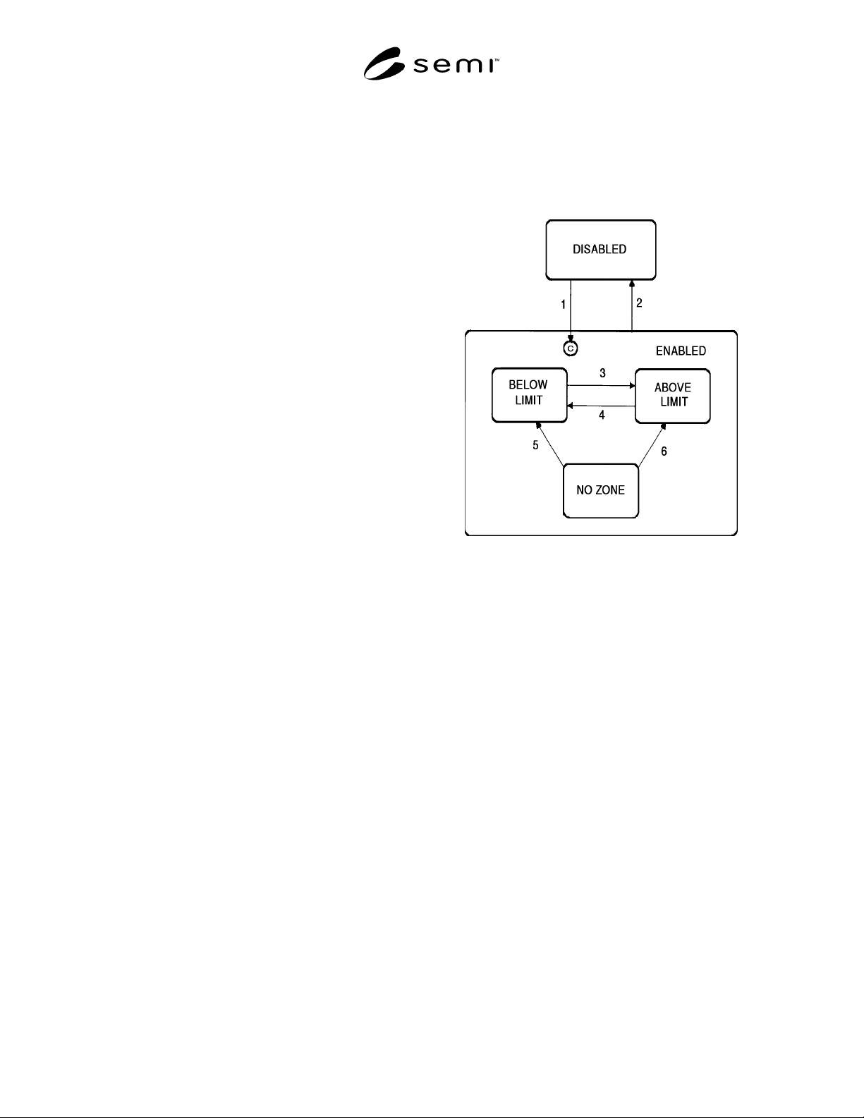
The functionality of each limit for each variable can be
described with the state model shown in Figure 4.2.3.
Below, the three states are described more fully,
followed by a table defining the transitions.
Figure 4.2.3
Limit State Model
ABOVE LIMIT
A variable is considered to be above a limit when its
value increases to equal or exceed the upper boundary
of the deadband, UPPERDB. The significance attached
to this state is a function of the host’s usage.
BELOW LIMIT
A variable is considered to be below a limit when its
value decreases to equal or fall below the lower
boundary of the deadband, LOWERDB. The
significance attached to this state is a function of the
host’s usage.
NO ZONE
In some circumstances it is possible for the variable
value to be in neither the upper zone nor the lower
zone. This may occur upon definition of a new limit or
upon equipment startup when the value of the variable
lies in the deadband. In this case, the active state of the
limit is considered to be NO ZONE. The limit shall
remain in this state until the variable value reaches
either boundary of the deadband.