semi合集-English.pdf - 第6068页
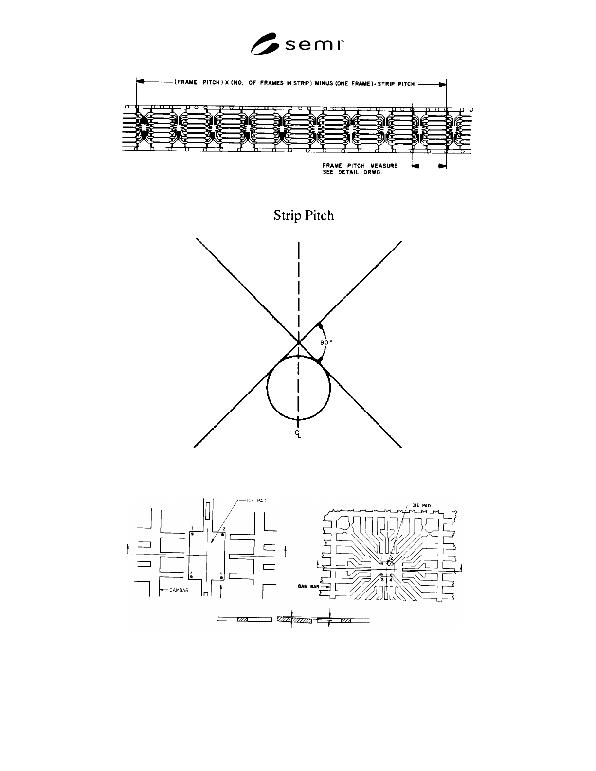
SEMI G10-96 © SEMI 198 6, 1996 5 Figure 2 Strip Pitch Figure 3 Pilot Hole Figure 4 Pad Tilt
SEMI G10-96 © SEMI 1986, 1996 4
17.1 Align overlay to travel axes within the resolution
of the instrument.
17.2 Position leadframe to overlay by optical methods.
17.3 Overlay targets will now be positioned to inspect
lead-flat location.
17.4 Pad outline will be positioned to inspect pad
location.
17.5 Metal-to-metal clearance is evaluated by use of
step gage against leadframe image on comparator
screen.
17.6 Traverse to specified distance to inspect cutoff
position.
18 Method for Coin-Depth Measurement
(See Figure 15)
18.1 Bend sample lead up for accessibility.
18.2 Measure material thickness beyond lead flat.
18.3 Measure material thickness within lead flat.
Difference between two readings is depth of coining.
19 Procedure for Measuring Lead Fatigue
Equipment — Automatic or manual lead fatigue tester
with 8 oz. ± .5 oz. weight.
19.1 Clamp leadframe strip on dambar of test frame
(see Figure 18).
19.2 Clamp 8 oz. weight on bottom-half of lead (see
Figure 19). Clamp must be at least L/2 from lead
shoulder.
NOTE: If lead is clamped too close to shoulder, a reduction in
measured lead strength will result, caused by twisting of
weight.
19.3 Turn on lead fatigue machine and set all counters
at zero.
19.4 Activate lead fatigue machine such that clamp
arm rotates through 90° ± 5° (see Figures 20 and 21).
This will result in actual bend of lead slightly less than
90°, depending on strength of metal.
19.5 Set machine to a two-to-five second cycle. One
cycle defined to be a 90° rotation and back.
19.6 Count number of complete cycles until metal lead
breaks and weight drops into pan.
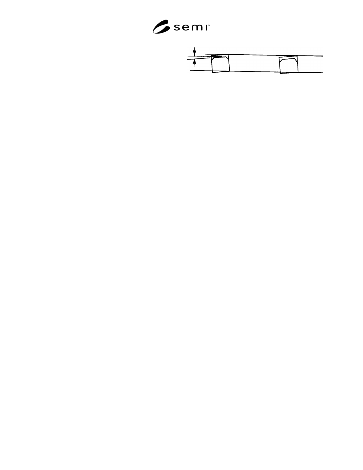
Figure 1
Lead Twist
SEMI G10-96 © SEMI 1986, 19965
Figure 2
Strip Pitch
Figure 3
Pilot Hole
Figure 4
Pad Tilt
SEMI G10-96 © SEMI 1986, 1996 6
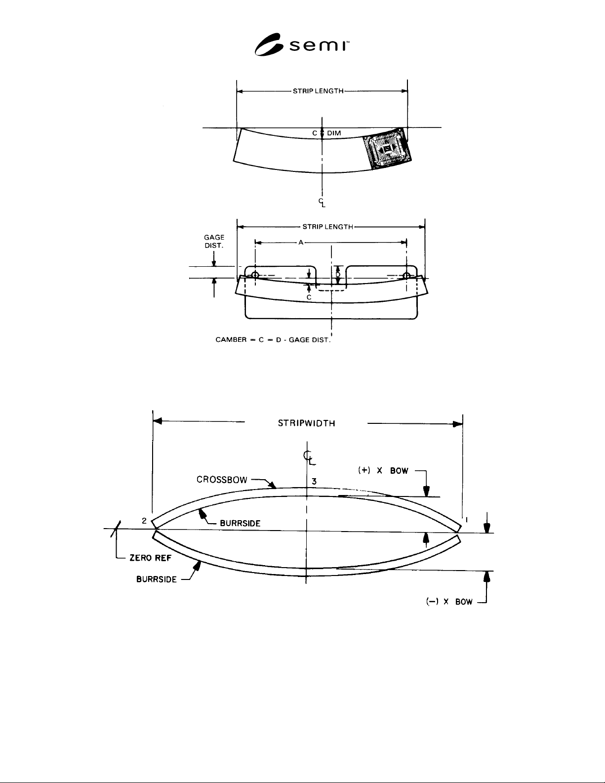
CAMBER IS REFERENCED TO DIMENSION A, NOT STRIP LENGTH.
STRIP LENGTH MUST BE LONGER THAN A.
Figure 5
Camber
Figure 6
Crossbow