semi合集-English.pdf - 第4545页
SEMI D26-1000 © SEMI 2000 4 Figure 2 Contact Array Cell
SEMI D26-1000 © SEMI 20003
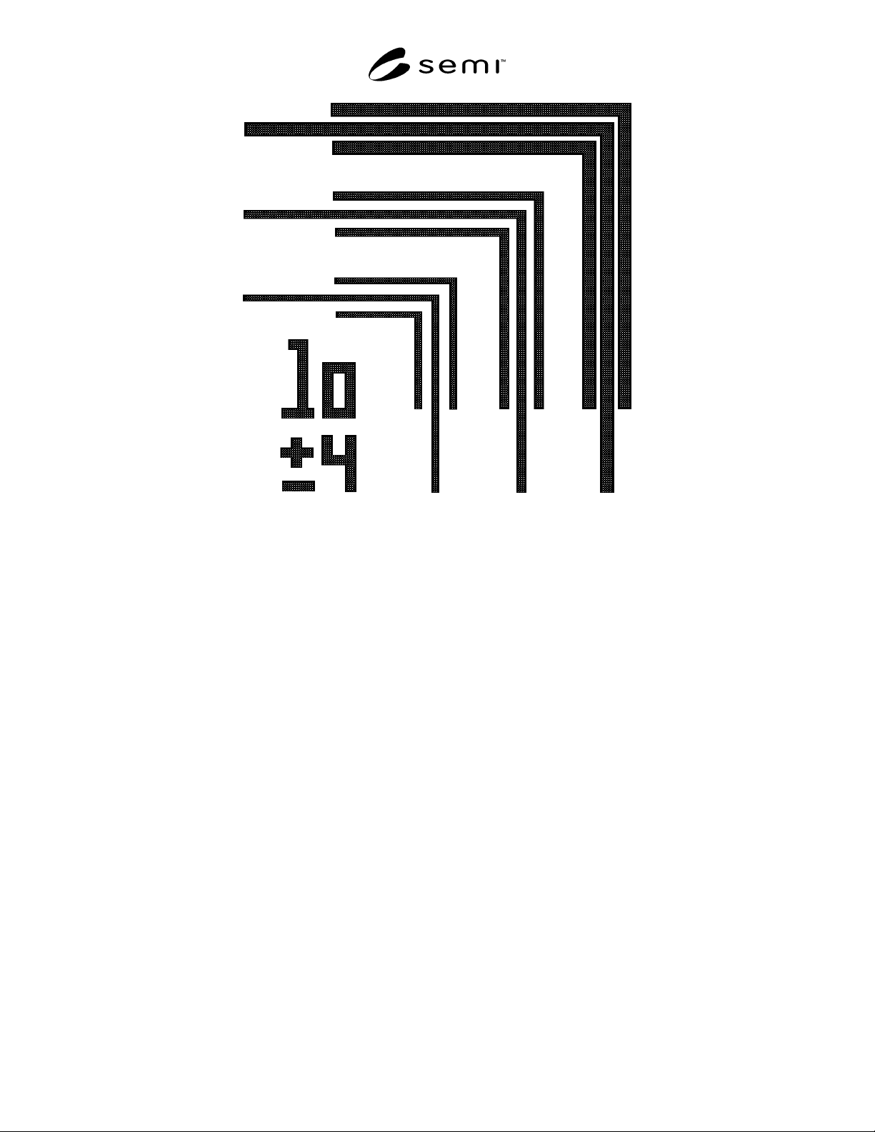
Figure 1
L-Bar Cell
SEMI D26-1000 © SEMI 2000 4
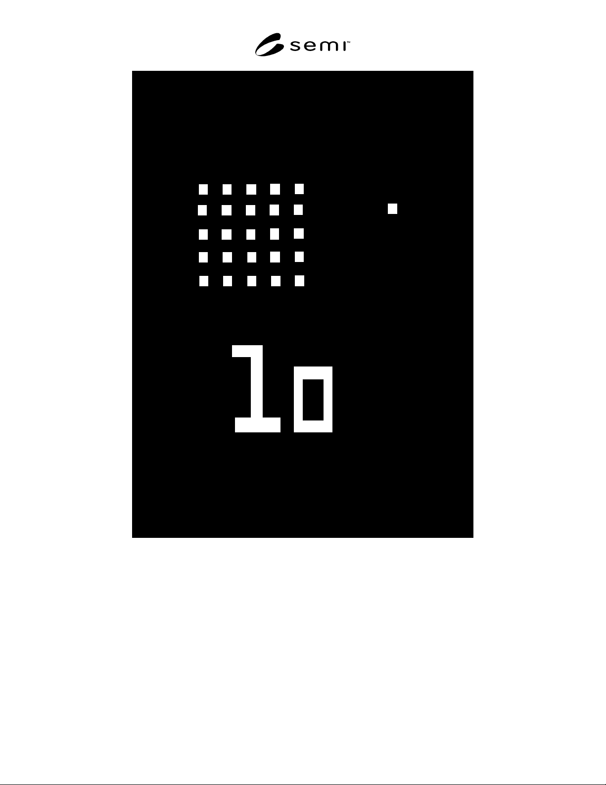
Figure 2
Contact Array Cell
SEMI D26-1000 © SEMI 20005
7.5 Centrality — This section defines the placement of
a patterned photo image onto a Mask Substrate relative
to known reference points. It is defined as the physical
(datum) position of a specific point on a photo pattern
relative to a separate point on the substrate designated
to be the photomask center.
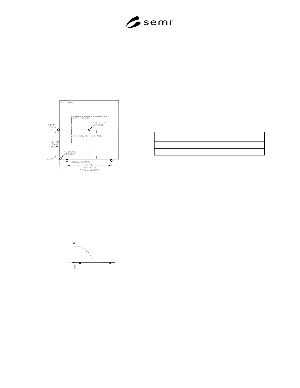
7.5.1 Requirements — Pattern Placement Tolerance ±
400µm in x and y relative to coordinates on the
photomask designated as center when referenced to the
0.000, 0.000 datum (see Figure 3).
Figure 3
Pattern Placement Tolerance
7.5.2 Reference 0.000, 0.000 — A datum identified as
a point on the extension of a line drawn between the
mask contact points on the bottom 2 pins, which is
directly below the mask contact point on the third pin
(see Figure 4).
Figure 4
Reference Datum
7.6 Pellicles (see SEMI P5)
7.6.1 For Polychromatic exposure systems: Shape,
Size, and Standoff of Pellicle
7.6.1.1 Shape — This is determined b y agreement
between the user and supplier.
7.6.1.2 Size — This is determined by agreement
between the user and supplier, but expression of
tolerance is as follows:
7.6.1.3 Outer diameter tolerance — + 0, -x
7.6.1.4 Inner diameter tolerance — + x, -0
7.6.1.5 Standoff — This is determined by agreement
between the user and supplier. But expression of
tolerance is as follows:
7.6.1.6 Tolerance — + 0, -x
Film Characteristics Polymer Films — Type - AR-
coated or non AR-coated (see Table 1)
7.6.1.7 Exposure Range — 360 nm - 440 nm.
7.6.1.8 Optical Transmission Rate — There are the
following two types depending on optical transmission
rate at an incident angle of 90° from surface of pellicle.
Table 1 Film Characteristics Polymer Films
Type Average Minimum
AR-Coated
≥ 94%
88%
Non-AR-Coated
≥ 91%
82%
7.6.1.9 Thickness — This is determined by agreement
between the user and supplier.
7.6.1.10 Thickness Conformity — This is determined
by agreement between the user and supplier.
7.6.1.11 Thickness Uniformity — This is determined
by agreement between the user and supplier.
7.6.1.12 Film Thickness — This is determined by
agreement between the user and supplier
7.6.1.13 Mechanical Strength — The requirements for
air blow are determined within ranges shown below:
• The air blow gun should be used; air pressure: ≤
2.1 kgf/cm
2
(at input of the air blow gun);
• Nozzle diameter of the air blow gun: ≤ 2 mm.
Distance between the nozzle tip and the film: ≥ 25
mm
7.6.2 Defect Limits — Maximum defect limits based
on the pellicle standoff and the numerical aperture of
the given type of exposure system are given in Table 1.
Any departure from these defect limits shall be agreed
to between supplier and user. Maximum defect limits
are given in Table 2.
7.6.2.1 Adhesives
7.6.2.1.1 Film Adhesive — Film must be sealed on the
entire top of the frame, with a minimum of 50% of the
frame width at any location.
7.6.2.1.2 Frame Adhesive — Frame adhesive must be
continuous and allow no gaps between pellicle frame
and adhesive and between adhesive and photomask