semi合集-English.pdf - 第337页
SEMI E49.6-1103 © SEMI 1995, 2003 3 7.3.3 A mutually agreeable quality program, includi ng sampling, shoul d be used to inspect and test component s and assemblies for parameters such as: surface contamination (e.g., hyd…

SEMI E49.6-1103 © SEMI 1995, 2003 2
5 Facility Guidelines
5.1 Gowning Area Class 10,000/1,000 (ISO Class 7/6)
for HP/UHP — All personnel working in cleanrooms
should wear paper booties prior to entering the gowning
area. Personnel should wear polyester gowns, hood, and
boots, pure latex or nitrile gloves (no talc), and safety
glasses before entering clean areas.
5.2 Materials Staging Area Class 10,000/1,000 (ISO
Class 7/6) for HP/UHP — Materials used in the
cleanroom should have the outer bag removed and the
inner bag wiped down with cleanroom wipes saturated
with a 50/50, 30/70, or 10/90 IPA/DI mix in the
materials staging area prior to entry into the cleanroom.
5.3 Assembly/Test Area Class 100 (ISO Class 5) for
HP and UHP — Welding cleanroom requirements must
be met per SEMI F78
5.4 Packaging Area Class 100 (ISO Class 5) for HP
and UHP
6 Utility System Guidelines
6.1 Purge Gases — Argon or nitrogen must be used for
purging gas systems during assembly and for testing,
using cryogenic source. Particle filtration should be
99.99999% removal of 0.003 µ m particles.
• Argon quality should meet the requirements of
SEMI C3.42.
•
Nitrogen quality should meet the requirements of
SEMI C59.
7 Materials Procedures
7.1 Procedures for Incoming Materials and
Components (Component Suppliers)
7.1.1 Identification Guidelines
7.1.1.1 Every deliverable item should have some
scheme of positive and permanent identification, so that
traceability is provided from the steel melt source to the
final metal finishing and packaging through site
installation.
7.1.1.2 This identification should provide
nondestructive post installation traceability.
7.1.1.3 Clearly visible labeling (without the need to
open the package) should be provided at each level of
packaging.
7.1.2 Packaging and Shipping Guidelines
7.1.2.1 Double bagging should be required. Multiple
inner bags are acceptable.
7.1.2.2 The inner bag should be cleanroom compatible
and should prevent damage from normal handling.
7.1.2.3 Vacuum sealing or dry inert gas purging should
be used on the inner bag.
7.1.2.4 The ends of the component should be protected
using some noncontaminating method.
7.1.2.5 The outer bag may be any suitable material.
7.1.3 Documentation
7.1.3.1 Components should be identified by lot number
or serial number.
7.1.3.2 Initial testing shall be conducted to qualify new
designs and processes including changes, as applicable.
The component manufacturer shall establish a
procedure for periodic monitoring of the manufacturing
process to ensure continual compliance to requirements
as noted in this guide. Documentation records must be
kept available for inspection for at least one year.
7.1.3.3 The equipment supplier should be responsible
for maintaining and supplying, upon request,
documentation that proves their components meet the
user’s materials performance requirements.
7.2 Receiving
7.2.1 All incoming material should be segregated from
“acceptable material” until it has been formally
accepted through documented procedure.
7.2.2 All cartons should be opened (100%); all goods
should be checked visually for damage (e.g., torn bags,
inadequate padding causing damage).
7.2.3 Material should be stored in original packaging.
Do not open until ready to use or inspect. Inspection
involving opening sealed plastic bags should be
conducted within the materials staging cleanroom.
After inspection, purge and heat-seal the material into a
clean polyethylene bag.
7.2.4 Any material failing initial inspection should be
immediately “red tagged” and set aside in a
“quarantine” area until the supplier of the material is
notified and disposition is determined.
7.3 Acceptance and Rejection of Incoming Material
7.3.1 All material should be identified by lot number or
serial number, allowing traceability back to source
documentation. All material should be identified with a
heat code, allowing traceability back to the raw material
heat. Only material so marked should be accepted.
7.3.2 All material should meet a purchasing
specification and be provided with documentation
demonstrating compliance. Only material so
documented should be accepted.

SEMI E49.6-1103 © SEMI 1995, 2003 3
7.3.3 A mutually agreeable quality program, including
sampling, should be used to inspect and test
components and assemblies for parameters such as:
surface contamination (e.g., hydrocarbon, particulate),
tubing quality, wall thickness, nicks, scratches; surface
roughness, pits, stringers, particle count, weldability,
helium leak rate (inboard/outboard/across seat), and
dimensions.
7.3.4 The material should be accepted only after these
incoming QA checks are completed.
8 Construction Procedures
8.1 Systems shall be constructed in accordance with
SEMI F78 and inspected per SEMI F81.
8.2 Subsystem Assembly Protocol
8.2.1 Gas panel and solvent system assembly should be
performed only by trained competent personnel.
8.2.2 Proper procedures for tightening face seal and
other connections, valve bonnets, regulator bonnets,
and other components should be followed at all times.
Manufacturers recommended assembly instructions
should be followed at all times.
8.2.3 To minimize entrained contaminants,
components and subassemblies should be capped or
under purge before and after assembly. Partially
assembled gas panels should be under purge or capped
at all times.
8.2.4 Assemblers should at all times be wearing clean
gloves; soiled, discolored or torn gloves should be
replaced immediately.
8.2.5 Components, assemblies or subassemblies which
are dropped or damaged during the assembly process
should be red-tagged and inspected before use. Face
seal gaskets which are dropped should be discarded.
9 Assembly Qualification and Quality
Assurance
9.1 Tests should be successfully completed and results
documented for all performance parameters (purity
indices) specified.
9.2 Leak rate tests should be conducted on 100% of all
subsystems per SEMI F1.
9.3 Design Qualification — Gas delivery system
design performance should be qualified in terms of two
parameters: particulate generation and contaminant
spike recovery. This testing should be performed on
the initial gas delivery system prototype and on any
design revision which significantly impacts the
component selection or system configuration. Test
results should be kept on file and made available to the
end user upon request.
9.3.1 Particulate Generation — Static and dynamic
particle testing should be performed in accordance with
SEMI F70 with a flow rate of at least 3 times the
maximum process flow rate at the recommended supply
pressure, except during mass flow controller testing
when test flow rates should be between 0% and 100%
of the MFC value. Testing should be performed on all
flow paths that differ significantly in components or
configuration. Dynamic test protocols should be as
follows:
• Each valve in the test flow path should be cycled
individually.
• Starting with the valve furthest upstream, cycle
each valve once every 20 seconds.
• MFC valves should be cycled from 0% to 100%.
9.3.2 Contaminant Spike Recovery — Contaminant
spike recovery testing should be performed on all flow
paths which differ significantly in configuration or
components. This test should be performed at a flow
rate equivalent to typical flow rates achieved in purge
and vent cycles for the specific flow path. Contaminant
spike recovery test protocols are:
• With all components placed in the full open
position, mass flow gas moisture level should be at
baseline for 30 minutes prior to testing to establish
stable background (< 20 ppbv per ASTM F 1397 or
< 500 pptv per SEMI F58).
• When a stable background is achieved, initiate a 2
ppm (v) moisture spike until the outlet moisture
concentration reaches 2 ppm. (Remove the
moisture source from the test gas, and monitor
elapsed time until moisture level reaches specified
level.)
9.4 Manufacturing Qualification — Manufacturing
qualification tests should be performed to verify the
manufacturing and quality control procedures followed
in the manufacturing of the gas delivery system. As the
configuration of gas systems varies greatly from
process to process, no specification should be given
here other than to state that static and dynamic particle
testing, moisture level, oxygen level, and hydrocarbon
testing should be performed to show that the gas
delivery system will meet the purity levels required.
9.5 Certification — Certification for gas delivery
system designs should include: leak rate certification,
particle counts with specified flow rates at specified
pressures and flow schematic indicating which flow
paths were tested and which components were cycled;
moisture level plotted against time with specified flow
SEMI E49.6-1103 © SEMI 1995, 2003 4
rates at specified pressures and flow schematic
indicating which flow paths were tested; and oxygen or
hydrocarbon levels plotted against time with specified
flow rates at specified pressures and flow schematic
indicating which flow paths were tested.
10 Labeling Protocol
10.1 All lines should be labeled by gas type and flow
direction.
11 Pre-Packaging Protocol
11.1 After testing is completed, the subassembly
should be pressurized with UHP grade Argon or N
2
.
Each process line should be sealed with a closed valve
and metal fitting cap or plug; all nonprocess lines
should be sealed with a plastic cap or plug before being
shipped.
11.2 Lines separate from gas system should be shipped
double bagged from the cleanroom. Bags should be
cleanroom compatible, and purged with inert gas, then
sealed from atmosphere.
12 Documentation Protocol
12.1 Documentation logs should be kept for all shop
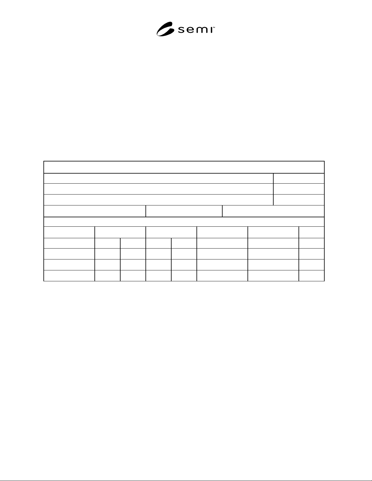
activities. Example log sheets are shown as Tables 1–5
below.
Table 1 Stainless Steel Component Inspection Log
Stainless Steel Component Inspection Log
Customer: Date:
Location: Page __ of __
Project: Cert: Yes/No
Date Received: Lot No.: Heat No.:
Description Wall Thickness Diameter Visual Surface Finish RA QA
Min. Max. Min. Max.