semi合集-English.pdf - 第5178页
SEMI M33-0998 © SE MI 1998 5 volatile compoun ds must n o t be applied (see the n ote in Section 14.7). 10 Calibration Pr ocedure SAFETY PRECAUT IONS — X-ray irradiation is dangerous . It is the respons ibilit y of the u…

SEMI M33-0998 © SEMI 1998 4
of the described method as reported in Section 15.13 of
this document.
7 Apparatus
7.1 The VPD treatment and contamination collection
particularly, but also the handling and measurement of
the specimen wafer is to be carried out in a specified
and controlled ambient (e.g., Cl. 10 (U.S. Federal
Standard 209)).
7.2 TXRF system equipped with:
— an X-ray source,
— a monochromator (preferable),
— a sample stage capable of manipulating in the x-,
y-, and z-direction,
— automated test specimen handling,
— an energy-dispersive spectrometer X-ray
detector,
— software sub-routine for glancing angle
calibration,
— software for baseline setting and for peak-fitting
and/or range-of-interest (ROI) peak finding
identification and evaluation, and
— analysis ambient without Ar background (see
Sections 6.10 and 7.1 of ASTM F 1526). The
system is preferably equipped with a flat/notch-
finder and quick-search option. For details, see
Section 6.10 of this document and Section 7.1 of
ASTM F 1526.
7.3 The VPD and the advisable dr ying chamber(s) will
have opening(s) made of polyvinylidenfluoride
(PVDF), polyfluoroalkoxyethylene (PFA), polyfluoro-
ethylene (PTFE) or similar resistant and pure polymer
materials that will not be attacked by HF. The
chamber(s) may contain one or more wafers on stacks.
The use of a drying chamber is advisable for the
preparation of the calibration reference microdroplet
(c.f., Section 10.1), but optional for the analysis
procedure. When a drying chamber is used, it must be
evacuable to below 1 kPa. After evacuation the
chamber is to be flushed with filtered N
2
until the
complete drying of the microdroplet residue is achieved
(see Section 9.1 of this document).
7.4 For the aliquots of standard stock and scanning
solutions validated micropipettes must be used.
Validation procedure can follow the requirements of
DIN 12650 Part 6.
8 Reagents and Materials
SAFETY PRECAUTIONS — Handling HNO
3
, HF and
H
2
O
2
is dangerous. Operators must comply with X-ray
safety regulations and be trained to wear protective
garments and glasses when handling HNO
3
, HF and
H
2
O
2
under efficient exhaust.
8.1 Ultra Pure Water, HNO
3
, HF, H
2
O — As
specified in ASTM D 5127, SEMI C7.3, C7.5, and
C7.6, respectively.
8.2 Standard Stock Solution — Ce rtified and traceable
standard reference “stock” solution with known
amount(s) of nitrate salt of the metals and sodium salt
of the non-metallic elements to be analyzed. Dilutions
have to be acidified with HNO
3
at pH ≤ 2. Note that the
shelf life of diluted solutions in the ppb-range of µg/L
or ng/L is less than 2 days.
8.3 Tested Scanning Droplet (Sections 4.5 and 6.12)
— 50 to 100 µL of ultra pure water or other scanning
solutions (e.g., aqueous HF (1 volume %) and H
2
O
2
(30
volume %)). The composition of the scanning droplet
must provide a controlled recovery rate above 90% for
each analyte, including Cu.
8.4 Blank Scanning Solution — Th e composition and
the amount of a scanning droplet without surface
impurities.
8.5 Microdroplet Residue — Microdroplet calibration
standard reference solution and/or scanning or
microdroplet of a liquid process medium dried at room
temperature under controlled conditions according to
Section 7.3. Above the microdroplet residue the
fluorescence count rate remains independent of
azimuthal position and of varying incident angle for
angles below 80% of the critical angle as described in
Section 15.6 of this document.
8.6 Surrogate Wafers — Polished or epitaxial wafers
used as carrier plates for scanning droplets collected
from other specimen wafers.
9 Preparation of Certified Reference
Microdroplet for Calibration Standard
9.1 Tested Preparation Conditions — Deposit
microdroplets containing 0.01 ng, 0.1 ng and 1 ng Ni in
Ni (NO
3
)
2
in 100 µL of a diluted standard stock
solution onto (a) hydrophobic (see Section 4.12 of this
document) polished or epitaxial wafer(s). Dry it (them)
under controlled conditions (e.g., in a drying chamber
at room temperature). When a drying chamber is used,
flush the chamber with a slow flow of N
2
for 20
minutes, then evacuate it (see Section 7.3 of this
document). The droplets must not explode or extend
during drying. They should not exceed an areal
dimension of 1 mm in any direction. Elements forming
SEMI M33-0998 © SEMI 19985
volatile compounds must not be applied (see the note in
Section 14.7).
10 Calibration Procedure
SAFETY PRECAUTIONS — X-ray irradiation is
dangerous. It is the responsibility of the user of this
standard to establish and maintain appropriate safety
and health practices and comply with the local
regulatory ordinance. The X-ray source must be
inactivated when beam path is unshielded. Operators
must be trained to avoid exposure to X-ray irradiation.
10.1 The calibration standard is a microdroplet of 100
µL of a diluted certified standard reference “stock”
solution. Note that the shelf life of diluted solutions in
the sub-ppb-range of µg/L or ng/mL is less than 2 days.
10.2 Locate the calibration standard microdroplet
residue and place it under the detector. Adjust the
glancing angle into the range where the fluorescence
count rate is independent of varying incidence angle
(see Section 8.5 of this document).
10.3 Position the detector window a s follows. Set
mapping or quick search parameters for covering the
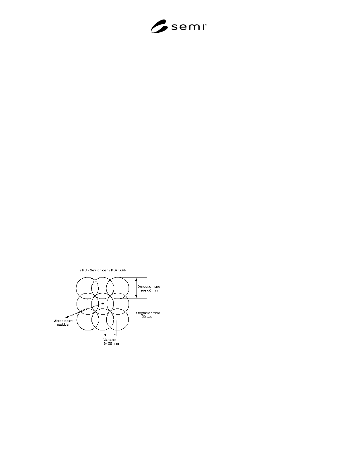
residue(s) with 3 × 3 detection spots (see Figure 1),
which are placed around the residue(s) as described in
Section 15.6 of this document. The mapped surface
must cover at least 95% of the square around the
residue(s) that is lying about in the center of the
detection spot. The analyzed part of microdroplet
residue under the detection spot must be higher than
95%.
Figure 1
VPD-Search VPD/TXRF
10.4 Set for mapping around the microdroplet residue
with a 50-sec integration time program at each
detection spot. Integrate at the maximum position(s) for
at least 1000 sec. These data provide the final result of
calibration due to the algorithm given in Section 13.6 of
this document.
10.5 Repeat calibration cycle (load-a nalyze-unload) at
least 3-times.
10.6 In order to distinguish relevan t results from
particle contamination from the environment and from
inefficient contamination collection, repeat
measurement on blank surface adjacent to the
microdroplet solution. The data are to be considered as
background data in the quantification algorithm (see
Section 15.12 of this document). For valid calibration,
background fluorescence counts must remain less than
20% of the fluorescence counts of microdroplet
residues, particularly, at lower areal densities (< 1 × 10
9
atoms/cm
2
).
10.7 The integrated fluorescence counts measured
with the specified Ni calibration standard can be
converted by known sensitivity factors into other
elements of interest as described in the References
section (see Sections 15.14 and 15.15 of this
document).
10.8 Keep the calibration standards in closed,
identifiable wafer holders in a clean room at room
temperature under conditions that will not change the
fluorescence reproducibility.
10.9 Optional linearity tests should deploy the
methods described in References section (see Section
15.16 of this document). Similar statistical linearity
tests can also be applied.
10.10 Upon the users request, the ab solute
instrumental calibration factor can be obtained. Due to
the Fresnel theory of X-ray absorption and
enhancement on pure metal (Ni) surfaces, the absolute
calibration can be carried out under specific optical
conditions. (See Referenced Documents section and
specifically Section 15.17.). Then, that absolute
calibration can be correlated to the external
microdroplet calibration.
11 Preparation Procedure
11.1 VPD treatment of the wafer su rface (Section
4.16) and the collection of contamination collection
with a scanning microdroplet (Section 4.5).
SAFETY PRECAUTIONS — Handling HF is
dangerous. It is the responsibility of the user of this
standard to establish and maintain appropriate safety
and health practices and comply with the local
regulatory ordinance. Operators must be trained to wear
protective garments and glasses when handling HF
under efficient exhaust.
11.2 In the VPD chamber wafers are treated with HF
vapor (e.g., isothermally distilled at room temperature
from an aqueous solution (20–50 volume %) within the
VPD chamber). The analytical specimen, the calibration

SEMI M33-0998 © SEMI 1998 6
droplet and the scanning droplet must be handled,
prepared and dried under specified and controlled
conditions. Drying means the evaporation of the
solvents on the wafer surface in a clean and controlled
environment without loosing analytes from the
microdroplet residue.
11.3 The wafers are exposed to the HF vapor in the
VPD chamber at room temperature. The exposure time
depends on the concentration of the HF used and on the
preceeding wafer treatment. The time has to be long
enough to ensure that the wafer surface will become
hydrophobic. After the HF treatment the solubilized
reaction products are collected by scanning a
microdroplet over the whole surface. Automatic
scanning is preferable (see Section 6.13 of this
document). The composition of the scanning solution is
optional but its volume and drying conditions should be
the same as under the preparation of calibration
standards (see Sections 8 and 15.18 of this document).
11.4 An example for tested preparation conditions
according to Section 15.18 of this document. A PTFE
or PFA petri dish of a diameter > 25 cm is filled with
20 volume % HF by mixing DI ultra pure water and 40
volume % HF of ULSI grade in a clean room ambient
of Cl 10 by U.S. Federal Standard 209. The petri dish is
positioned in the bottom of the VPD chamber, loaded
with specimen wafers. The wafers are exposed to the
HF wafer at room temperature. Exposure time is
between 30 minutes and 6 hours. Longer exposure
times can lead to deliberate etching. After the HF
treatment the solubilized, reaction products are
collected by rolling a scanning microdroplet over the
whole surface. Automatic scanning is preferable. Please
refer also to Section 4.5 and Section 8.3 of SEMI E45.
11.5 Rinse the validated micropipette at least 5 times
with ultra pure water or with the selected scanning
solution. Then fill the micropipette with the required
amount of ultra pure water or with the scanning
solution. For scanning surfaces with thicker silicon
oxide (> 300 nm) only about 50 µL of scanning
solution is sufficient. The microdroplet to be dried for
analysis should not extensively (+10%) exceed 100 µL
together with the VPD reaction products.
11.6 Put the scanning microdroplet on the wafer
surface and roll the scanning microdroplet around the
wafer edge 2 times and then over the whole surface in a
zigzag pattern. Automatic equipment can scan in a
spiral pattern with overlapping paths (see Section 6.13).
An edge exclusion of less than 1 mm is attainable for
manual or automatic scanning. Edge exclusion is well
below 1 mm at automatic scanning.
11.7 Position the scanning microdro plet in the center
of the wafer.
11.8 For monitoring the cleanliness of the VPD
preparation and contamination collection and that of the
analytical ambient, put the same volume of the blank
scanning solution, as applied to the preparation of the
calibration standard (100 µL under tested preparation
conditions), with the validated micropipette onto the
scanned specimen surface at least 3 cm off the position
of the scanning solution. For valid results fluorescence
counts above the blank must remain less than 20% of
the fluorescence counts above the droplet residues. Use
ultra pure water (100 µL) for blanks of process
chemical and media samples. If the scanning solution
consists only of ultra pure water of controlled quality,
no blanks are required.
NOTE: In the absence of oxidation agent(s), Cu recovery
rates can be reduced (see Section 15.18).
11.9 Dry the wafers as specified in Sections 7.3, 9.1,
and 11.2 of this document.
12 Analysis Procedure
12.1 Localize the microdroplet residues of the
collected scanning solution or the microdroplet residues
of the liquid process medium and the microdroplet
residue of the blank scanning solution. Detect
fluorescence counting rates above these microdroplet
residues and above the scanned blank surface under the
instrumental parameter adjusted for calibration. The
quantification algorithm is given in Section 13.6.
Integrated counts above both the blanks and the VPD
prepared surface must not exceed 20% of the integrated
counts above the microdroplet residue of the collected
scanning solution (see Section 9.6 of this document).
13 Quantification Procedure
13.1 The instrument must run unde r established
statistical process control (e.g., as described in Section
15.19 of this document).
13.2 Before releasing results, quote instrumental
parameters such as:
• rotating or sealed anode,
• voltage and current applied to the X-ray source,
• characteristic excitation line(s) of the incident X-
ray,
• glancing angle(s),
• type of monochromator,
• amount [ng] or [number of atoms] of e.g., Ni in the
calibration standard reference microdroplet,
• location of the microdroplet(s) analyzed,
• peak evaluation technique (ROI or peak-fitting),