semi合集-English.pdf - 第704页
SEMI E92-0302 E © SEMI 1999, 2003 7 BOLT S/ Ligh t Pl ane Rear Vi ew z101 =402 ±1 z102 =478 ±1 Seal zone (side interface feature) Floor Horizontal datum plane (E15.1_H) z109 =402 ±2 z107 =480 ±1 z111 =45 ±2 y110 (E63-y 7…
SEMI E92-0302
E
© SEMI 1999, 2003 6
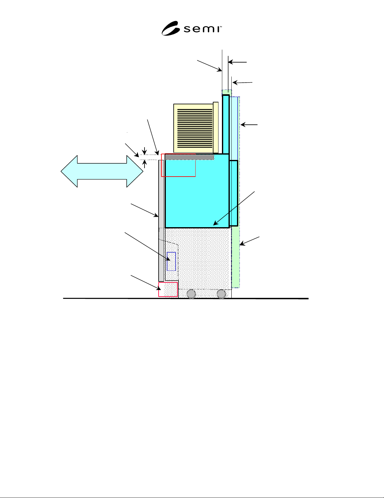
SEMI E15.1 Compatible Equipment
Boundary
SEMI E84
Forklifts exclusion volume
Reduce Reserved
Space
Parallel I/O for AMHS
Communication
BOLTS/M Plane
BOLTS/M image
(Adopter)
Cart to SEMI E15.1
Docking Interface Port
BOLTS/Light Plane
SEMI E15.1 Compliant Load
Port Height
Equipment panel
Slide In/Out
CIDRW
BOLTS/
Light
BOLTS/Light
Shelf
Bottom interface
plane
Figure 1
Diagram Concept of Light-Weight and Compact Box Opener/Loader and Tool-Interoperability Standard
(BOLTS/Light)
SEMI E92-0302
E
© SEMI 1999, 2003 7
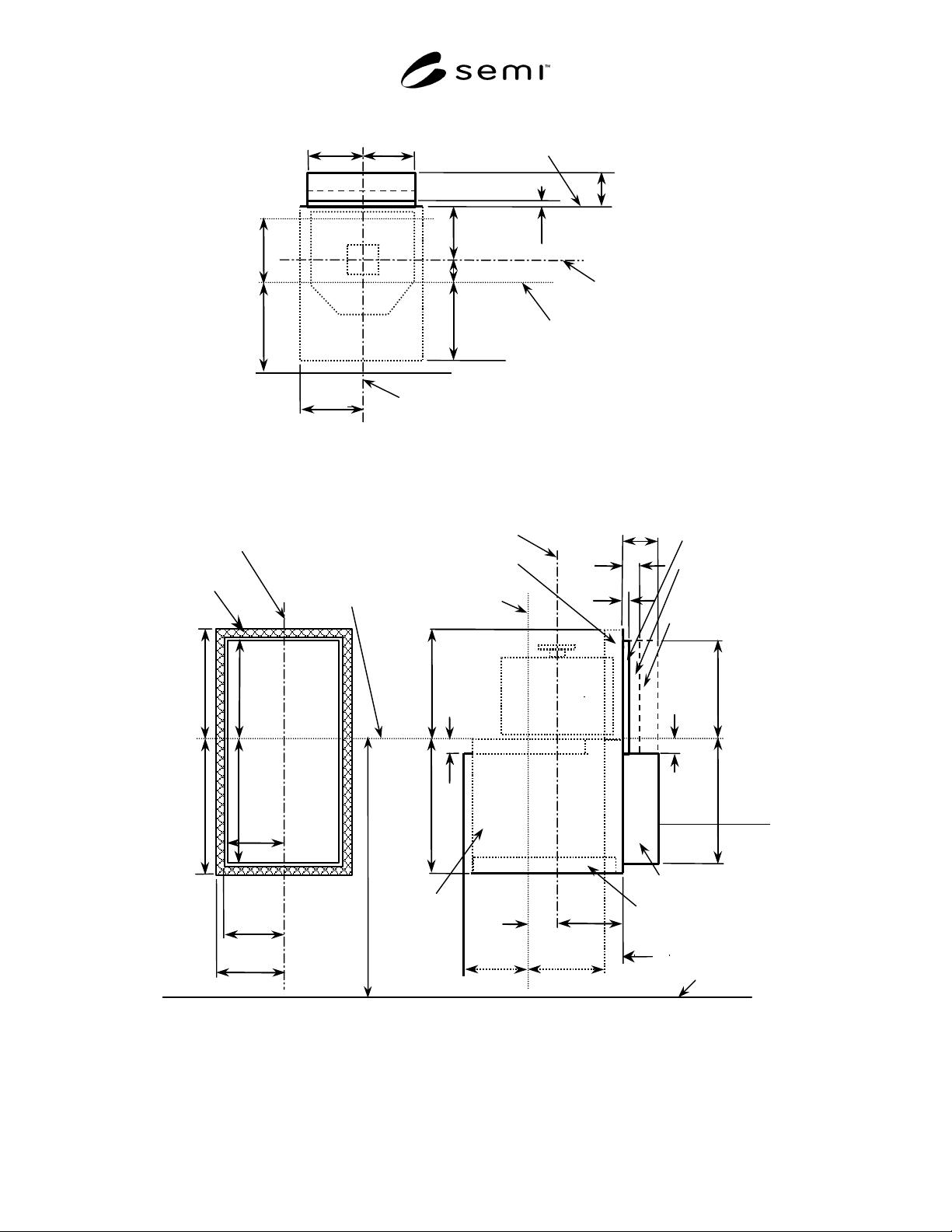
BOLTS/Light Plane
Rear View
z101
=402 ±1
z102
=478 ±1
Seal zone (side
interface
feature)
Floor
Horizontal
datum plane
(E15.1_H)
z109
=402 ±2
z107
=480 ±1
z111
=45 ±2
y110
(E63-y76)
y102
≥
80
y103
≥
3
y101
=170 ±2
Side View
(E15.1_D)(E15.1_D1)
z103
≥
394
z108
=45 ±2
z105
≥
470
Reserved space when
door is opening or
closing
Reserved space when
door is closed
Bilateral datum plane
Facial datum plane
(Undock position)
x101=200 ±1
x103=207± 1
z103
≥
394
z105
≥
470
z106=471±1
x102
≥
199
y112
≥
31
Top
View
x101
=200 ±1
x102
≥
199
(E15.1_D1)
(E15.1_D)
y110 (E63_y76)
y111
=220 ±2
x108
=207 ±1
Bilateral
datum plane
y101
=170 ±2
Facial datum plane
(Undock position)
y102
≥
80
y103
≥
3
Docked Facial datum plane
(Docked position)
BOLTS/Light Plane
Docked Facial datum
plane (Docked position)
Door seal exclusion volume
BOLTS/Light
opening exclusion
volume
Permanent reserved
space
Loader
exclusion
volume
The loader bottom flange
exclusion volume (see Fig.3)
z104=395±1
Figure 2
Top, Rear, and Side Views of BOLTS/Light Exclusion Volume and Equipment Side of the Side Interface
Feature
SEMI E92-0302
E
© SEMI 1999, 2003 8
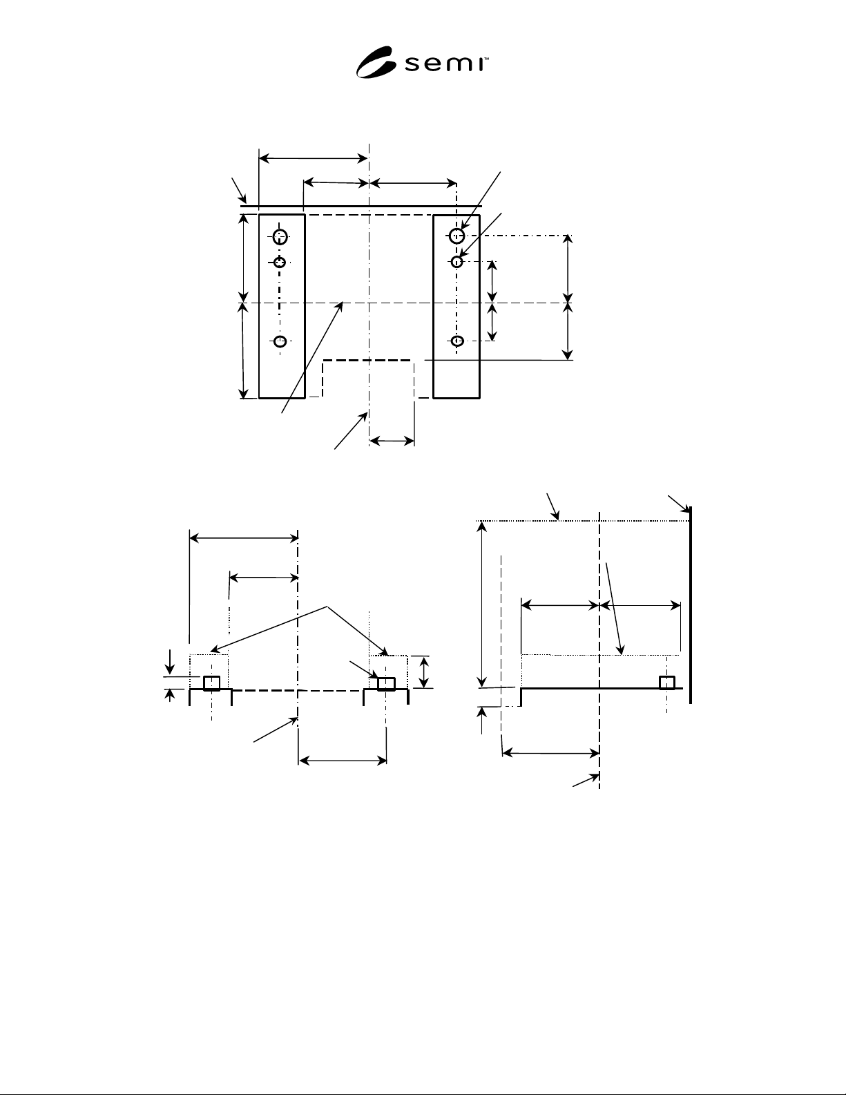
Top View
Facial datum plane
(Undock position)
Bilateral
datum plane
Front View
Side View
Horizontal
datum plane
z110
=10 ±1
z112
≥
15
z107
=480 ±1
ISO M8x16H
Thread for locking screws (4x)
d1=12 ±0.05(PIN 2x)
y106
=180 ±0.05
y109
=110 +0/-5
y107
=100 ±0.3
y108
=100 ±0.3
Seal zone
y104
=200 +0/-10
y105
=220 +0/-10
x104=235 ±2
x105=200 ±2
x106
=220 ±0.05
x107
=175 +5/-0
[E15.1_D]
Facial datum plane
(Undock position)
Bilateral
datum plane
d1=12 ±0.05(PIN 2x)
x106
=220 ±0.05
y105
=220 ±10
x108
= 207±1
x109
≥
235
y115
≥
220
z113
≥
30
y116
≥
200
Seal zone
the loader
bottom flange
exclusion volume
the loader bottom
flange exclusion volume
Figure 3
Equipment Side of the Bottom Interface Feature