semi合集-English.pdf - 第2395页
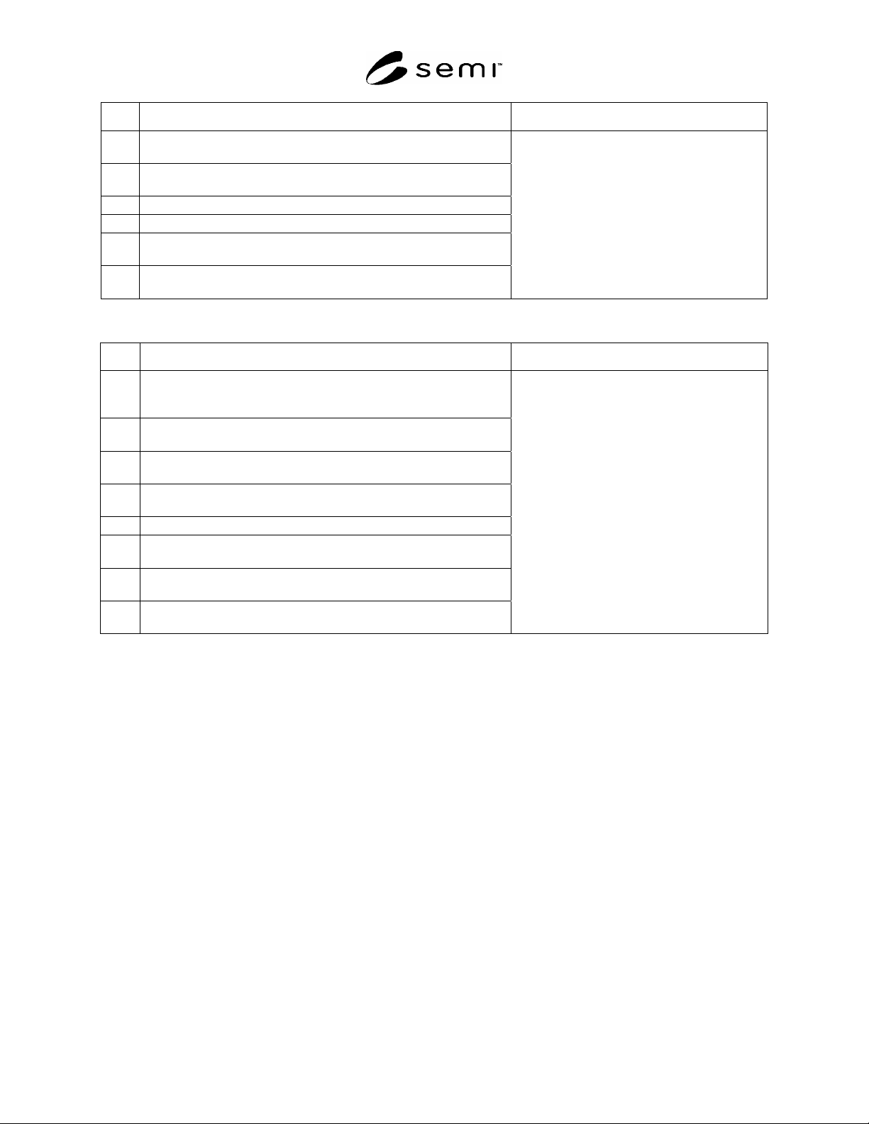
SEMI E84-0305 © SEMI 1999, 2005 39 No. Error Description OHS Reaction 3 Anytime during the load op eration the load pres ence status on the loader does not match th e actual conditions o f the current operatio n. 4 The R…
SEMI E84-0305 © SEMI 1999, 2005 38
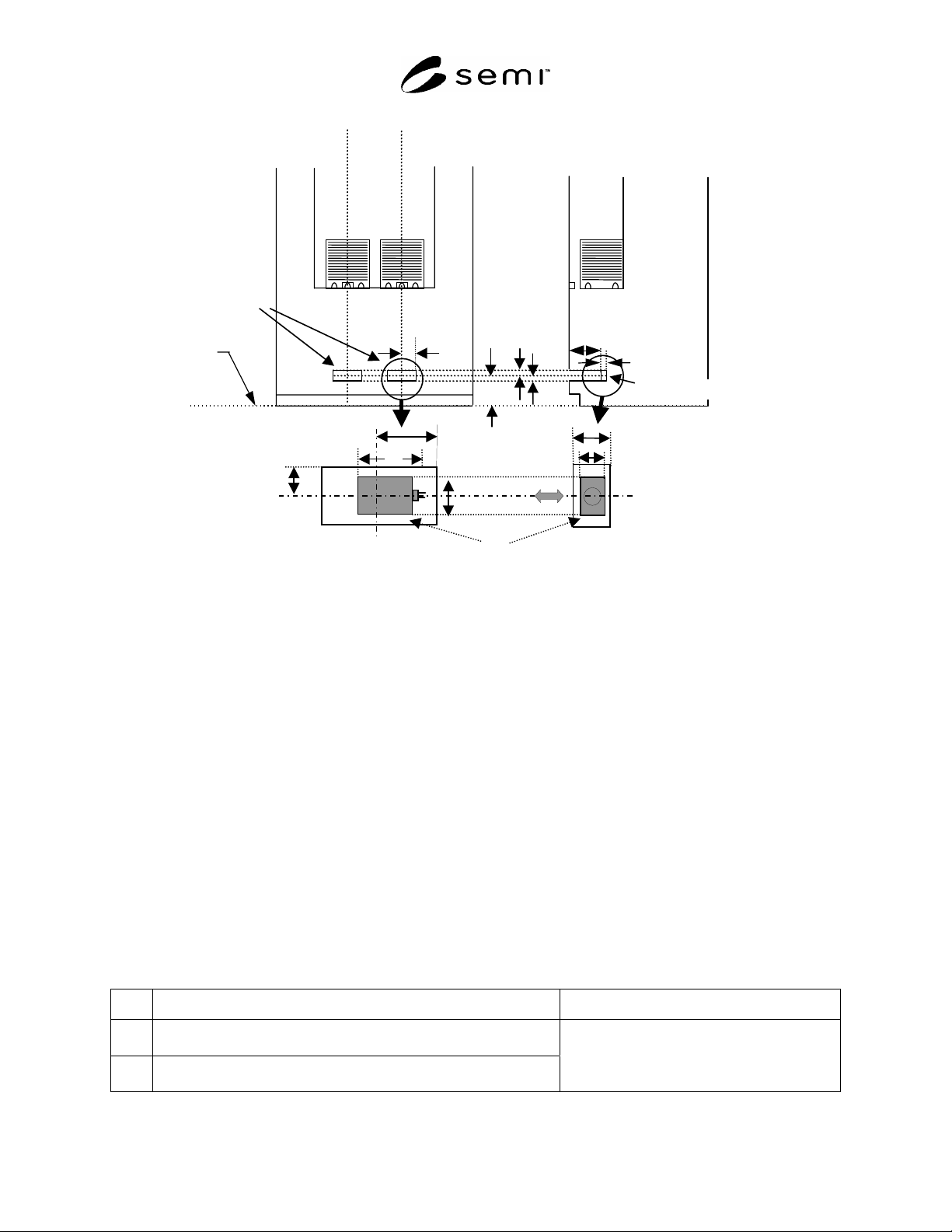
floor
D7
D8
H7
W8
H8
Exclusion
Volume for
Parallel I/O
Device
Center of Optical beam
PI/O interface sensor unit
Beam direction
H
W
W8
H8
D8
D
Figure A1-5
Example of the PI/O Interface Sensor Unit Implementation at Load Port for AGV/RGV
A1-1.8 Equipment Integration Test Mode — It is recommended that the passive equipment provide a method to
disable any physical carrier engagement/movement after the SEMI E84 sequence (example carrier clamping on the
load port and docking to the FIMS port) on a load port by load port basis. This functionality will support equipment
level testing of automated carrier transfers and SEMI E84 communications at load ports.
A1-2 Reticle Loadport Connector Locations
A1-2.1 For equipment with reticle carrier loadports, if the connection for automated delivery to the equipment is
made using an electrical connector, the connector should be located on the top of the equipment outside of the
easement for overhead transport. The connector should be no more than 600 mm from the edge of the easement.
A1-3 Additional Interbay AMHS Information
A1-3.1 This section describes error generation and recovery examples (mainly for active equipment) for interbay
AMHS (i.e., OHS, stockers). The following are errors that could conceivably occur during transfer operations (load,
unload). The procedures are designed for a technician with considerable knowledge of AMHS equipment. Error
recovery should always follow the recovery procedures specified in the equipment manuals.
A1-3.2
OHS (Active Type) Error Examples
Table A1-1 Load Operation Errors
No. Error Description OHS Reaction
1
The L_REQ does not go OFF in the allotted amount of time during a
load transaction.
2
Anytime during the transfer a load operation failure or stop positioning
failure is detected.
The load operation sequence is stopped and an
error is displayed.
SEMI E84-0305 © SEMI 1999, 2005 39
No. Error Description OHS Reaction
3
Anytime during the load operation the load presence status on the
loader does not match the actual conditions of the current operation.
4
The READY signal does not go ON within the specified amount of
time after the TR_REQ signal is output.
5 The READY signal goes OFF during the load operation.
6 The L_REQ signal remains ON after the load operation is completed.
7
The READY signal does not go OFF within the specified amount of
time after the COMPT signal is output.
8
Anytime during the load operation the optical transmission beam is
interrupted.
Table A1-2 Unload Operation Errors
No. Error Description OHS Reaction
1
The OHS moves to the stocker (for an unload operation) and outputs
the VALID signal, but the U_REQ signal remains OFF for a specified
amount of time.
2
Anytime during the transfer an unload operation failure or stop
positioning failure is detected.
3
Anytime during the unload operation the load presence status on the
loader does not match the actual conditions of the current operation.
4
The READY signal does not go ON within the specified amount of
time after the TR_REQ signal is output.
5 The READY signal goes OFF during the unload operation.
6
The U_REQ signal remains ON after the unload operation is
completed.
7
The READY signal does not go OFF within the specified amount of
time after the COMPT signal is output.
8
Anytime during the unload operation the optical transmission beam is
interrupted.
The unload operation sequence is stopped and
an error is displayed.
A1-3.2.1 Example of the Signal Status When an Error is Generated During Transfer Operations
A1-3.2.1.1 OHS Side Error Generation
A1-3.2.1.1.1 OHS Side Signals — When an error is generated, the BUSY signal must stay ON. This is to prevent
secondary accidents due to the other device operating on its own.
A1-3.2.1.1.2 Stocker Side Signals — When an error is generated, each signal (except for the READY signal) should
remain in the status it was in at the time of the error. The READY signal should go OFF.
A1-3.2.1.2
Stocker Side Error Generation
A1-3.2.1.2.1 Stocker Side Signals — When an error is generated, each signal should remain in the status it was in at
the time of the error.
The READY signal should be OFF.
The ES signal should be OFF.
HO_AVBL should be OFF.
A1-3.2.1.3 OHS Side Signals — When an error is generated, only the BUSY signal should go ON. All remaining
signals should go OFF.
SEMI E84-0305 © SEMI 1999, 2005 40
A1-3.2.2 Recovery Sequences
A1-3.2.2.1 Should an error occur during transfer operations (refer to Tables 1 and 2), the recovery should begin by
returning the carrier to the stocker or OHS. Then, the error should be recovered. The four recovery scenarios are:
1. Load operation, carrier is returned to the stocker.
2. Load operation, carrier is returned to the OHS.
3. Unload operation, carrier is returned to the stocker.
4. Unload operation, carrier is returned to the OHS.
A1-3.2.3 Recovery Method
A1-3.2.3.1 OHS Side
In the case of sequence 2 (above), the load/unload sequence should be started over from the beginning.
In the case of sequence 3 (above), the corresponding transfer operation should be canceled.
In the case of sequences 1 and 4 (above) the corresponding transfer operation should be considered completed.
A1-3.2.3.2 Stocker Side
In the case of sequences 1 and 4 (above) the corresponding transfer operation should be considered completed.
In the case of sequences 2 and 3 (above), the load/unload sequence should be started over from the beginning.
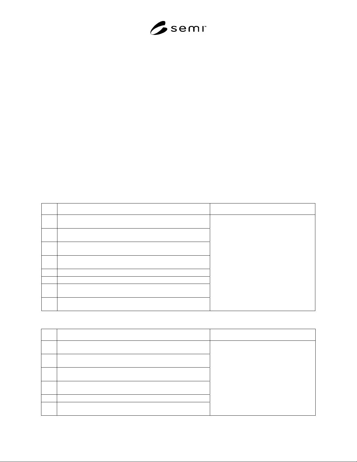
Table A1-3 Load Operation Errors
No. Error Description Stocker Reaction
1
The L_REQ does not go OFF in the allotted amount of time during
an unload transaction.
2
Anytime during the transfer a load operation failure or stop
positioning failure is detected.
3
Anytime during the load operation the load presence status on the
loader doesn't match the actual conditions of the current operation.
4
The READY signal does not go ON within the specified amount of
time after the TR_REQ signal is output.
5 The READY signal goes OFF during the load operation.
6 The L_REQ signal remains ON after the load operation is completed.
7
The READY signal does not go OFF within the specified amount of
time after the COMPT signal is output.
8
Anytime during the load operation the optical transmission beam is
interrupted.
The load operation sequence is stopped and an
error is displayed.
Table A1-4 Unload Operation Errors
No. Error Description Stocker Reaction
1
The stocker (for an unload operation) outputs the VALID signal, but
the U_REQ signal remains OFF for a specified amount of time.
2
Anytime during the transfer an unload operation failure or stop
positioning failure is detected.
3
Anytime during the unload operation the load presence status on the
loader doesn't match the actual conditions of the current operation.
4
The READY signal does not go ON within the specified amount of
time after the TR_REQ signal is output.
5 The READY signal goes OFF during the unload operation.
6
The U_REQ signal remains ON after the unload operation is
completed.
The unload operation sequence is stopped and
an error is displayed.