semi合集-English.pdf - 第5497页
SEMI P7-0997 © SEMI 1982, 2003 1 SEMI P7-0997 (Reapproved 1103) METHOD OF VISCOSITY DETERMIN ATION, METHOD A — KI NEMATIC VISCOSITY This method was technically reapproved by th e Gl obal Micropatterning Comm ittee and is…
SEMI P6-88 © SEMI 1988, 1996 4
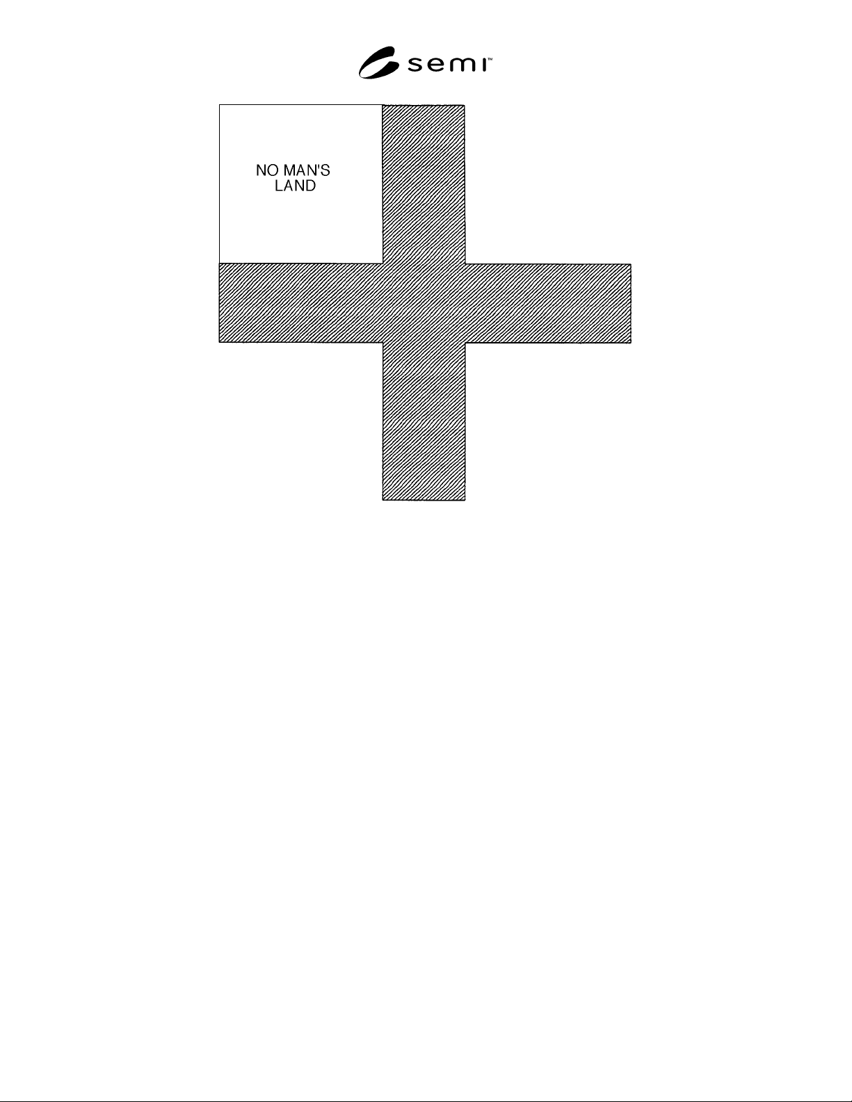
Figure 3
No Man’s Land
NOTICE: These standards do not purport to address safety issues, if any, associated with their use. It is the
responsibility of the user of these standards to establish appropriate safety and health practices and determine the
applicability of regulatory limitations prior to use. SEMI makes no warranties or representations as to the suitability
of the standards set forth herein for any particular application. The determination of the suitability of the standard is
solely the responsibility of the user. Users are cautioned to refer to manufacturer’s instructions, product labels,
product data sheets, and other relevant literature respecting any materials mentioned herein. These standards are
subject to change without notice.
The user’s attention is called to the possibility that compliance with this standard may require use of copyrighted
material or of an invention covered by patent rights. By publication of this standard, SEMI takes no position
respecting the validity of any patent rights or copyrights asserted in connection with any item mentioned in this
standard. Users of this standard are expressly advised that determination of any such patent rights or copyrights, and
the risk of infringement of such rights, are entirely their own responsibility.
Copyright by SEMI® (Semiconductor Equipment and Materials
International), 3081 Zanker Road, San Jose, CA 95134. Reproduction o
f
the contents in whole or in part is forbidden without express written
consent of SEMI.

SEMI P7-0997 © SEMI 1982, 2003 1
SEMI P7-0997 (Reapproved 1103)
METHOD OF VISCOSITY DETERMINATION, METHOD A — KINEMATIC
VISCOSITY
This method was technically reapproved by the Global Micropatterning Committee and is the direct
responsibility of the North American Microlithography Committee. Current edition approved by the North
American Regional Standards Committee on July 27, 2003. Initially available on www.semi.org October
2003; to be published November 2003. Originally published in 1982; previously published in September
1997.
1 Scope
1.1 This method, a simplified version of ASTM D 445
and ASTM F 66 is intended for determining the
kinematic viscosity of photoresists by measuring the
time for a volume of liquid to flow under gravity
through a calibrated glass capillary at a fixed
temperature. Efflux time is measured in seconds and
multiplied by the calibration constant of the viscometer
to obtain kinematic viscosity in units of centistokes
(cSt). Optionally, kinematic viscosity may be multiplied
by the density of the photoresist to obtain dynamic
viscosity in units of centipoise (cP). Refer to
ASTM D 445 and F 66 for additional information and
definitions.
NOTICE: This standard does not purport to address
safety issues, if any, associated with its use. It is the
responsibility of the users of this standard to establish
appropriate safety and health practices and determine
the applicability of regulatory or other limitations prior
to use.
2 Referenced Standards
2.1 ASTM Standard
1
D 445 — Kinematic Viscosity of Transparent and
Opaque Liquids (and the Calculation of Dynamic
Viscosity)
F 66 — Photoresist Used in Microelectronic
Fabrications
NOTICE: Unless otherwise indicated, all documents
cited shall be the latest published versions.
3 Apparatus
3.1 Calibrated Viscometer — Of the glass capillary
type. (A listing of such viscometers is given in Table 1,
ASTM D 445.)
3.2 Constant Temperature Bath — Equilibrated to
25.0 ± 0.1° C.
1 American Society for Testing and Materials, 100 Barr Harbor
Drive, West Conshohocken, Pennsylvania 19428-2959, USA.
Telephone: 610.832.9585, Fax: 610.832.9555, Website:
www.astm.org
3.3 Viscometer Clamp — Adjustable to achieve
vertical alignment.
3.4 Thermometer — Graduated in 0.1° C intervals and
calibrated (see ASTM D 445 and ASTM F 66).
3.5 Stopwatch — Readable in 0.2 second intervals or
better.
3.6 Chemicals — Acetone, chromic acid, methyl ethyl
ketone, xylene.
4 Procedure
4.1 Confirm that the constant temperature bath is
equilibrated to 25.0 ± 0.1° C.
4.2 Select a clean dry viscometer of appropriate
viscosity range. Choose the proper tube size for the
given viscosity so that the efflux time is greater than or
equal to 200 seconds.
4.3 Charge the viscometer with photoresist in the
manner dictated by the design of the viscometer and
wipe clean.
4.4 Insert the viscometer into the clamp holder in the
constant temperature bath. Vertical alignment of the
viscometer is essential for proper flow measurement.
4.5 Allow 15 minutes for the sample temperature to
equilibrate.
4.6 Use suction or pressure to adjust the level of the
test sample to a position in the capillary arm about 5
mm ahead of the first timing mark.
4.7 With the sample flowing freely, measure the time
for the meniscus to pass from the first timing mark to
the second. Record the time in seconds.
4.8 Repeat the steps in Sections 4.6 and 4.7. (For
reverse flow viscometers, use the same or another
viscometer and begin with the step in Section 4.3 for
the second measurement.)
4.9 The two measurements must agree within 0.5
seconds. If they do not agree, then reject the
measurement results.
4.10 After the measurement, the viscometer should be
flushed several times with a suitable solvent (methyl

SEMI P7-0997 © SEMI 1982, 2003 2
ethyl ketone or acetone for typical novolac positive
resists or equivalent and xylene for rubber based
negative resists or equivalent).
4.11 Dry the tube by blowing dry, filtered air through
the viscometer for a few minutes.
4.12 The viscometer should periodically be cleaned
with chromic acid to remove trace organic deposits.
5 Calculation
5.1 Average the flow measurements.
5.2 Kinematic viscosity in cTs = Viscometer constant
× efflux time in seconds.
5.3 Dynamic viscosity in cP = Photoresist density at
25.0° C in g/mL × kinematic viscosity in cSt.
NOTICE: SEMI makes no warranties or
representations as to the suitability of the standards set
forth herein for any particular application. The
determination of the suitability of the standard is solely
the responsibility of the user. Users are cautioned to
refer to manufacturer’s instructions, product labels,
product data sheets, and other relevant literature
respecting any materials mentioned herein. These
standards are subject to change without notice.
The user’s attention is called to the possibility that
compliance with this standard may require use of
copyrighted material or of an invention covered by
patent rights. By publication of this standard, SEMI
takes no position respecting the validity of any patent
rights or copyrights asserted in connection with any
item mentioned in this standard. Users of this standard
are expressly advised that determination of any such
patent rights or copyrights, and the risk of infringement
of such rights, are entirely their own responsibility.
Copyright by SEMI® (Semiconductor Equipment and Materials
International), 3081 Zanker Road, San Jose, CA 95134. Reproduction o
f
the contents in whole or in part is forbidden without express written
consent of SEMI.