semi合集-English.pdf - 第4553页
SEMI D26-1000 © SEMI 2000 12 Figure 10 Data Mat rix Code Field in Edge Exclusion Area NOTICE: SEMI makes no warranties or representations as to the su itability of the standard s set forth herein for any particular appli…
SEMI D26-1000 © SEMI 200011
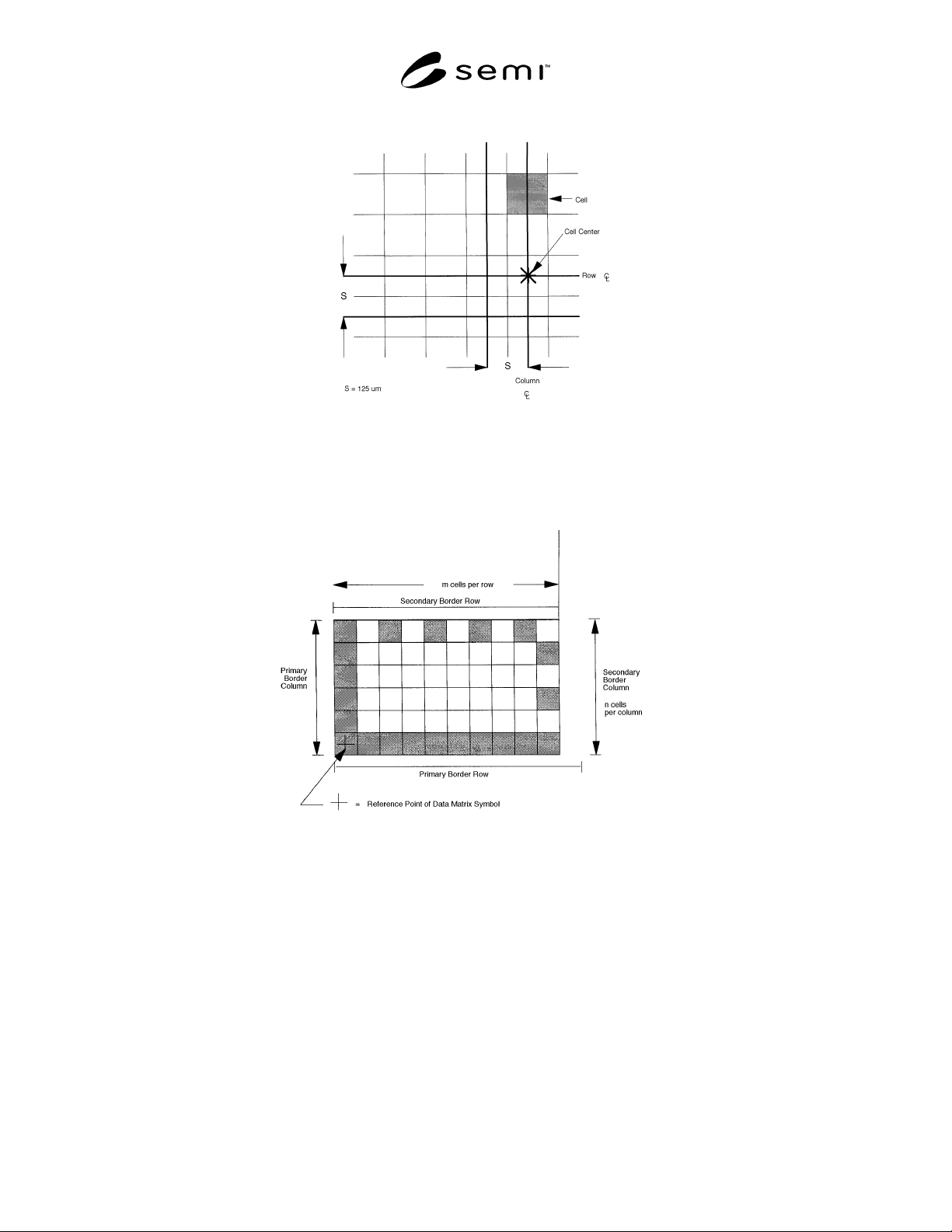
Figure 8
Data Matrix Cell Dimensions
Figure 9
Border Rows and Columns
SEMI D26-1000 © SEMI 2000 12
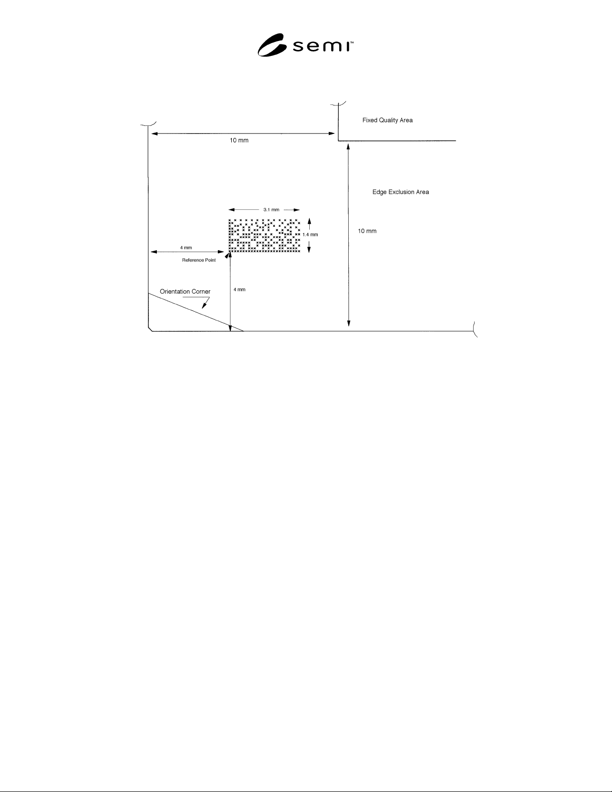
Figure 10
Data Matrix Code Field in Edge Exclusion Area
NOTICE: SEMI makes no warranties or representations as to the suitability of the standards set forth herein for any
particular application. The determination of the suitability of the standard is solely the responsibility of the user.
Users are cautioned to refer to manufacturer’s instructions, product labels, product data sheets, and other relevant
literature respecting any materials mentioned herein. These standards are subject to change without notice.
The user’s attention is called to the possibility that compliance with this standard may require use of copyrighted
material or of an invention covered by patent rights. By publication of this standard, SEMI takes no position
respecting the validity of any patent rights or copyrights asserted in connection with any item mentioned in this
standard. Users of this standard are expressly advised that determination of any such patent rights or copyrights, and
the risk of infringement of such rights, are entirely their own responsibility.
Copyright by SEMI® (Semiconductor Equipment and Materials
International), 3081 Zanker Road, San Jose, CA 95134. Reproduction o
f
the contents in whole or in part is forbidden without express written
consent of SEMI.

SEMI D27-1000 © SEMI 20001
SEMI D27-1000
GUIDE FOR FLAT PANEL DISPLAY EQUIPMENT COMMUNICATION
INTERFACES
This guide was technically approved by the Global Flat Panel Display Committee and is the direct
responsibility of the North American Flat Panel Display Committee. Current edition approved by the North
American Regional Standards Committee on August 28, 2000. Initially available at www.semi.org August
2000; to be published October 2000.
1 Purpose
1.1 This is a guide for implementing equipment
communication features for successful integration and
automation in a flat panel display manufacturing
facility.
2 Scope
2.1 This guide includes references to other SEMI
standards. It also includes definitions and explanations
specific to FPD equipment automation.
2.2 The scope of this guide is limited to equipment
communication features that interface with factory
automation systems.
2.3 This guide does not reference physical or electrical
interfaces, except to the extent necessary to implement
the features described. For example, a serial data cable
connector could be specified to have 9 pins or 25 pins.
2.4 This guide may not be applicable to all types of
FPD equipment. It only applies to those for which a
direct data communication interface will be
implemented between the equipment and the factory
automation systems.
2.5 This guide does not address all software standards
that may be applicable, but addresses a subset that is
necessary for effective integration and automation.
2.6 This standard does not purport to address safety
issues, if any, associated with its use. It is the
responsibility of the user of this standard to establish
appropriate safety and health practices and determine
the applicability of regulatory limitations prior to use.
3 Limitations
3.1 The other SEMI standards referred to in this
document have been carefully reviewed for
applicability to FPD manufacturing. However, when
referring to other SEMI standards used in this
specification, the reader should allow for some editorial
exceptions in order to apply the specification to FPD
equipment. For example, if another SEMI specification
referenced here uses the term “wafer”, the reader can
assume that this also applies to FPD substrates, and
likewise with “silicon” and glass or plastic. These
minor differences in no way impact the interpretation or
implementation of those standards in FPD
manufacturing equipment and factory systems.
3.2 This guide is not an all-inclusive list of applicable
standards, but is a starting point for defining
requirements of these equipment automation functions,
and a guideline for implementation.
4 Referenced Standards
NOTE 1: As listed or revised, all documents cited shall be the
latest publications of adopted standards.
4.1 SEMI Standards
SEMI E4 — SEMI Equipment Communications
Standard 1 Message Transfer (SECS-I)
SEMI E5 — SEMI Equipment Communications
Standard 2 Message Content (SECS-II)
SEMI E23 — Specification for Cassette Transfer
Parallel I/O Interface
SEMI E30 — Generic Model for Communications and
Control of SEMI Equipment (GEM)
SEMI E37 — High-Speed SECS Message Services
(HSMS), Generic Services
SEMI E37.1 — High-Speed SECS Message Services,
Single-Session Mode (HSMS-SS)
SEMI E84 — Specification for Enhanced Carrier
Handoff Parallel I/O
5 Terminology
5.1 The following define some descriptive terms that
can be used to refer to systems that meet the
requirements of the standards referenced herein.
5.1.1 SECS Compliant — This term is often used to
describe systems which comply completely with both
the SEMI E4 (SECS-I) and SEMI E5 (SECS-II)
standards. However, it is more appropriate to identify
the system as “SECS-I Compliant” and/or “SECS-II”
compliant. This distinction is important because SECS-
II can be implemented independently from SECS-I. The
term “SECS Compliant” is ambiguous, but commonly
used. It is suggested that the following terms be used