semi合集-English.pdf - 第3425页
SEMI E133-0705 © SEMI 2004, 2005 6 the following criteria are applied to test wh ether or not a given set of capabilities cons titutes a valid PCS functional group. Specifically, a functional group should satisfy on e or…
SEMI E133-0705 © SEMI 2004, 2005 5
Table 3 Method Definition Table Format
# Method Arguments Returns Requirement Behavior/Comment
Y or N
7.2.9.1 Method — Method name.
7.2.9.2 Arguments — Input parameters.
7.2.9.3 Returns — Output parameters.
7.2.9.4 Requirement — Is this method required of a compliant implementation? Y – Yes, or N – No.
7.2.9.5 Behavior/Comment — Summary description of the method’s purpose and behavior, explanation of expected
system response to this method, etc.
7.3 Data Types
7.3.1 The following data types may be used in this specification to describe the form of an attribute or other similar
high level definitions. Note that extensions to the Process Control System interface specifications are not limited to
the list of data types defined in this specification.
Any — The format may be any of the others listed in this section. Format is determined by the implementation.
Binary — A sequence of bytes that may have any value. Binary values are sometimes called “unformatted”
because their structure is not apparent.
Boolean — Takes the value of “true” or “false.”
Checksum — A checksum value calculated on a specific stream of data using a specific method of calculation.
Enumeration — A format that allows a specified list of possible values. In this document, these values are
represented as text strings, but may be implemented differently (e.g. as integers that correspond to the named
values).
Status – The Status type is a structure that contains information about whether or not an error that has occurred
in a transmission and information on the type of error. The form of the structure is given in §9.
Integer — A numeric value, Integers are always whole numbers. The form and number of bytes is left to the
implementation definition.
list of xxx — An item that can hold multiple instances of a specified type (where xxx is the data type).
Real — A numeric value that may represent any whole or fractional number. The form and number of bytes is
left to the implementation definition.
Text — A text string. Limitations on length are left to the implementation technology unless otherwise
specified in this document. Strings are recommended to be implemented as UTF-8.
Time — Representation of the date and time of the occurrence of interest. The structure and form of items of
this type is left to the implementation.
7.4 Sequence Behavior
7.4.1 Sequence behavior description is specified in the form of UML Sequence Diagrams.
7.5 State Behavior
7.5.1 State behavior description is specified in the form of UML State Charts.
8 Overview
8.1 Using the simple definition of a Functional Group given in the Terminology section, the initial set of PCS
functional groups has been identified. To identify the proper scope (and therefore the boundaries) for these groups,
SEMI E133-0705 © SEMI 2004, 2005 6
the following criteria are applied to test whether or not a given set of capabilities constitutes a valid PCS functional
group. Specifically, a functional group should satisfy one or more of the following requirements:
Support a coherent set of tasks
Share common set of data and must use it under similar constraints (performance, retention, etc.)
Internal objects are tightly coupled
Legacy implementation/integration constraints exist (for example, the capabilities are inseparable because an
external system must interact with them as an integrated whole)
Strong associations exist in the market (that is, one would expect these capabilities to be provided as an
integrated product)
8.2 Based on theses criteria, and the stated implementation priorities of the semiconductor manufacturers and
suppliers involved on the task force, the following initial PCS functional groups have been identified:
R2R (Run-to-Run) Control
FD (Fault Detection)
FC (Fault Classification)
FP (Fault Prediction)
SPC (Statistical Process Control)
8.3 Note that it is understood that other PCS functional groups can be added as needed. Future versions of the
document will describe procedures for adding a new group.
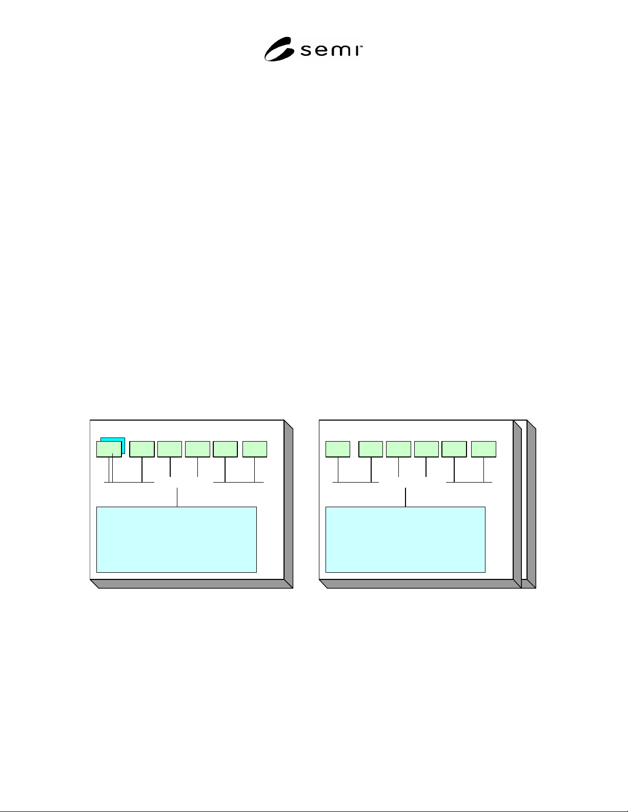
8.4 The aforementioned groups can be implemented at the tool or factory level or both. As a requirement,
functional group interfaces should be defined in a consistent way. The following diagram represents the proposed
functional groups and an example of their interactions within the factory and tool environments.
PCS Functions in the “Equipment”
R2R FD FC FP SPC ...
Equipment Specific
Tool Control System
- Process Modules
- Integrated Metrology
- Sensors
- User Interface
- E-Diagnostics
- ...
PCS Functions in the “Factory”
R2R
R2R FD FC FP SPC ...
Factory Specific
Manufacturing Execution Systems
- Recipe Management
- Dispatch
- Automated Material Handling
- E-Diagnostics
- ...
PCS Functions in the “Equipment”
R2R FD FC FP SPC ...
Equipment Specific
Tool Control System
- Process Modules
- Integrated Metrology
- Sensors
- User Interface
- E-Diagnostics
- ...
Figure 1
PCS Functions
8.4.1 Process Control Systems may consist of a variety of capabilities or functions at both the factory and
equipment level as shown in Figure 1. Moreover, this may include multiple instances of the same function type
from different suppliers. In the example above, several run-to-run controllers are running at the factory level with
differences that are only visible as internal special capabilities. This interface standard will facilitate easier
collaboration between the tool level functions and factory level systems independent of the supplier that developed
the internal function’s capabilities.

SEMI E133-0705 © SEMI 2004, 2005 7
9 Process Control Systems Functional Group Capabilities and Interface Data Structures
9.1 Functional Group Partitioning
9.1.1 Process control systems are partitioned into functional groups using the criteria defined in §8. This standard
defines the interface data structures, services and behavior associated with these functional groups. In this section
the capabilities of the PCS functional groups are defined in more detail. First of all, the basic capabilities common
to all
functional groups are presented. Then the additional basic capabilities unique to each functional group are
presented. A high level description of the specifications of data structures, services and behavior are described in
§10.
9.1.2 It is important to note that the specific implementations of these various functional groups may differ greatly
in the level of capability delivered, performance, quality of service, and internal architecture. Moreover, in a given
factory, there may be multiple instances of the same functional group running concurrently, from one or more
suppliers. Some functional groups may be completely independent of other PCS functional groups (in other words,
they can operate in relative isolation, depending only on information from systems external to PCS); others may
depend heavily on other functional groups, collaborating closely to provide a higher level of capability than they
could on their own.
9.1.3 The goal of the PCS interface standards is to enable all of these implementation scenarios (and more) without
dictating internal product architectures.
9.2 PCS Analysis Engine
9.2.1 As defined in §8, all functional groups can be thought of as specializations of a PCS Analysis Engine and
therefore inherit the structure and behavior of a PCS Analysis Engine. This section defines the common capabilities
of a PCS Analysis Engine.
9.2.2 General Capability Description
9.2.2.1 All PCS Analysis Engines shall have inputs and outputs as shown in Figure 2. This means that the PCS
Analysis Engines shall support the consumption of the specified inputs and production of the specified outputs as
necessary to achieve the required capabilities of that analysis engine as specified in this standard. These inputs and
outputs are specified as aggregate data structures. The structures are aggregated into “collection types” according to
the category of data. A definition of these collection types is provided in Table 4. The PCS Analysis Engine shall
have the general behavior of utilizing specified inputs, performing tasks based to some degree on these inputs, and
generating outputs. Any additional structure and behavior of various PCS Analysis Engines are outlined in the
remainder of this section and specified in detail in ¶10.4.
9.2.2.2 Note that, in addition to limitations of specification defined in §4, the following are beyond the scope of
definition of the PCS Analysis Engine:
the level of synchronization of inputs with performance of tasks and/or generation of outputs, and
the specification of any internal states of the PCS Analysis Engine.
9.2.2.3 All PCS Analysis Engines belonging to this functional group shall have the capabilities listed in Table 5.