semi合集-English.pdf - 第4257页
SEMI F78-0304 © SEMI 2003, 2004 10 B egin Productio n Welding Verify correct w elding po w er supply a nd weld head, collets , electrodes, etc. Yes Is equipm e nt work ing properly ? Yes Set up procedure to deal with h a…
SEMI F78-0304 © SEMI 2003, 2004 9
Tube
Size
Wall
Thickness
Minimum
ID Purge Rate
ID Purge
Pressure
Restrictor
Size
38 to 64 mmwc
½ in.
12 mm
0.049 in.
1 mm
15 scfh
7 l/m
1.9 to 2.8 torr
1.0 to 1.5 iwc
25 to 38 mmwc
¼ in.
6mm
¾ in.
20 mm
0.065 in.
1.5 mm
20 scfh
10 l/m
1 to 2 torr
0.5 to 1.1 iwc
13 to 28 mmwc
¼ in.
6 mm
1 in.
25 mm
0.065 in.
1.5 mm
40 scfh
20 l/m
1 to 1.9 torr
0.5 to 1.0 iwc
13 to 25 mmwc
¼ in.
6 mm
1 ½ in.
38 mm
0.065 in.
1.5 mm
80 scfh
40 l/m
1 to 1.3 torr
0.5 to 0.7 iwc
13 to 18 mmwc
¼ in.
6 mm
2 in.
50 mm
0.065 in.
1.5 mm
150 scfh
70 l/m
0.7 to 1.3 torr
0.4 to 0.7 iwc
13 to 18 mmwc
3/8 in.
10 mm
3 in.
75 mm
0.065 in.
1.5 mm
320 scfh
150 l/m
0.4 to 0.9 torr
0.2 to 0.5 iwc
5 to 13 mmwc
½ in.
12 mm
4 in.
100 mm
0.083 in.
2 mm
600 scfh
275 l/m
0.4 to 0.7 torr
0.2 to 0.4 iwc
5 to 13 mmwc
¾ in.
20 mm
6 in.
150 mm
0.083 in.
2 mm
1000 scfh
475 l/m
0.2 to 0.9 torr
0.2 to 0.5 iwc
5 to 13 mmwc
¾ in.
20 mm
NOTE 1: scfh—standard cubic feet per hour. L/m—liters per minute. iwc—inches of water column. mmwc—millimeters of water column.
NOTE 2: This table is for use on butt welds only.
NOTE 3: Internal pressure shall be adjusted for ID convexity of 0 to +10% of the wall thickness at the 6 o’clock position (bottom of the weld).
NOTE 4: ID purge rates shall be adjusted to the desired ID color line.
NOTE 5: Restrictor sizes are approximate. Purge rate and pressure are critical parameters.
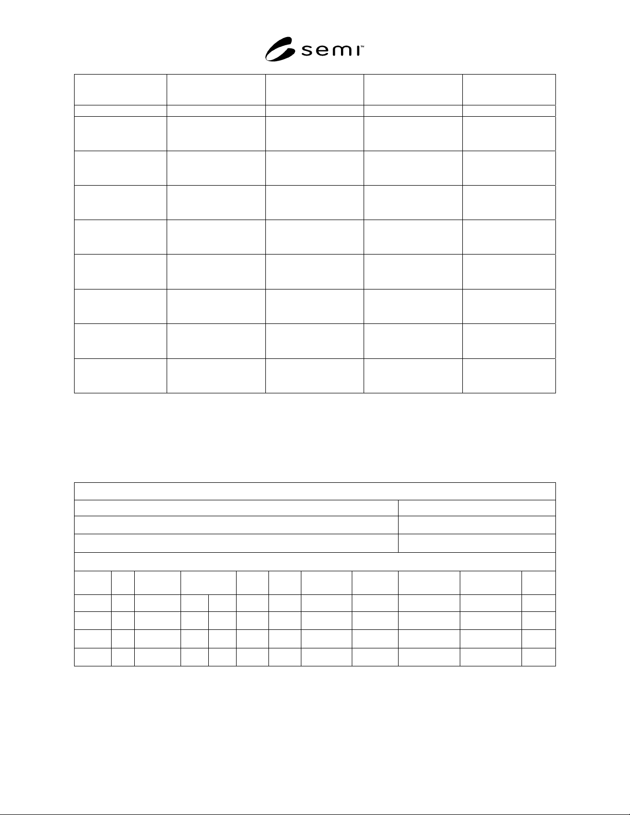
Table 2 Weld Log or Weld Coupon Log
Customer: Date Begun:
Location: Page __ of __
Project: Welder:
Number Size Description ID Purge
Flow/pressure
Visual Color Uniformity Heat/Lot Coupon Date Comments QA
SEMI F78-0304 © SEMI 2003, 2004 10
B
egin Production
Welding
Verify correct welding power
supply and weld head, collets,
electrodes, etc.
Yes
Is equipment
working properly?
Yes
Set up procedure to deal
with hazard. Reference
SEMI Standards.
Yes
Fix it, call technician,
or return to factory.
Are there any hazardous
materials or operations?
N
o
N
o
Do all materials conform to
specifications? Tubing, fittings,
cleaned and faced? Electrode
t
yp
e,
g
as
p
urit
y
,
p
ur
g
e set-u
p
?
Get proper materials
and material specs.
Submit test welds for
testing. Document results
and record all variables
on proper forms.
N
o
Has Weld Procedure Been Qualified?
Are Welders Certified?
Make Qualification Test
welds for WPS, PQR,
P
Q
R Per Section 7.
N
o
Yes
Yes
Yes
Make Sample Test Welds using
cleaned and faced coupons of
same alloy, material heat and
dimensions to be welded.
Examine Sample Welds on OD for weld
bead appearance, joint contamination,
Joint soundness, surface oxidation,
discoloration, pitting, cracking, defects
of fit-up and workmanship.
Section coupons and inspect ID surface
visually for penetration, bead concavity,
b
ead variation, and oxidation.
Is weld acceptable?
Determine
and fix cause
of problem
First sample weld is onsite
work sample. Document all
variables. Identify and save
all coupons.
Enter
required
information
in coupon
log.
N
o
Verify correct
OD, ID purge
flowrates and
ID pressure.
At start or end
of shift or after
a change in
procedure. See
Section 11.
Weld Inspection
100% Visual of OD
surface of all welds.
ID inspection of all
accessible welds;
cut-out statistically
significant sample
for inspection.
Repair or cut out previous
welds
p
er Sectio
n
13.4.
Is weld acceptable?
Maintain Weld
Log for all welds
N
o
Yes
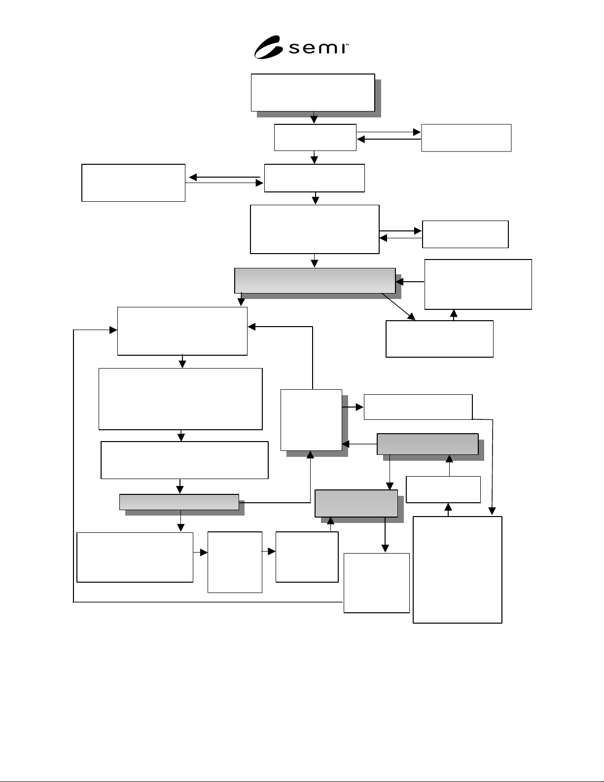
Figure 2
Welding Procedure Flow Chart
SEMI F78-0304 © SEMI 2003, 2004 11
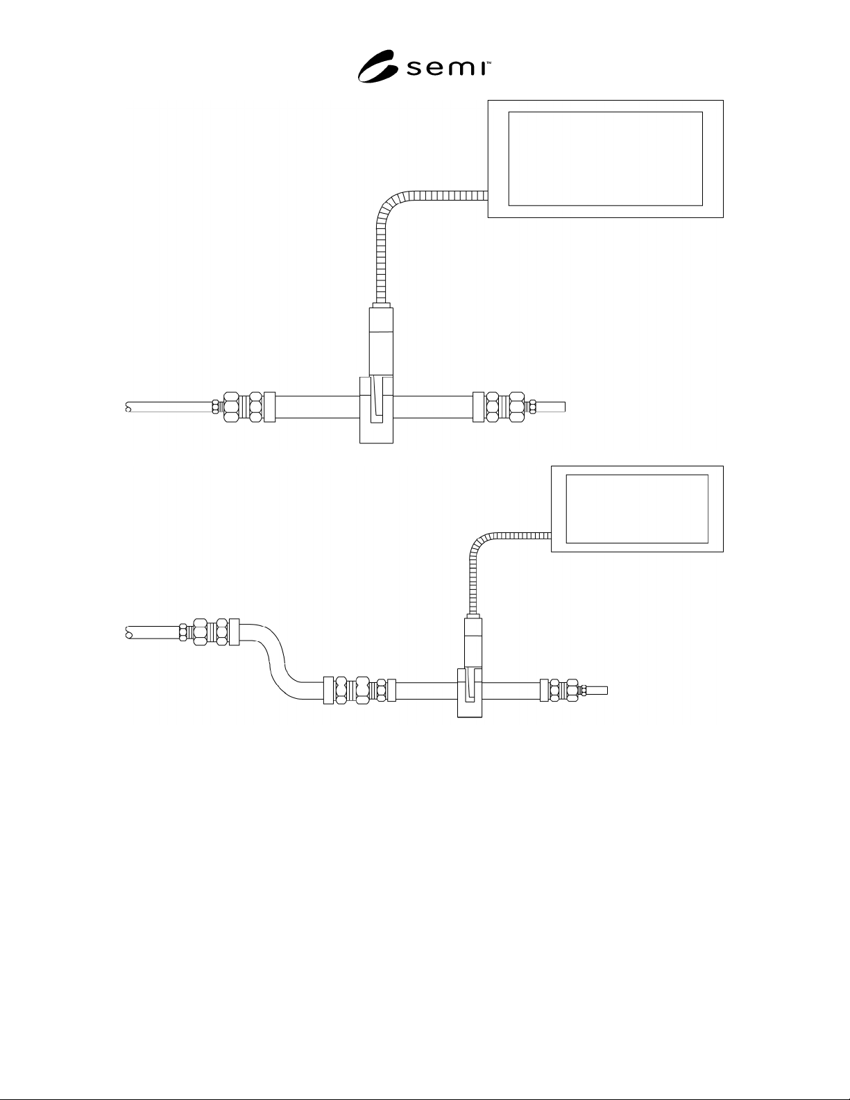
(a) Preferred.
(b) Alternate.
Figure 3
All Couponing Shall Use the System ID Purge Gas