semi合集-English.pdf - 第2366页
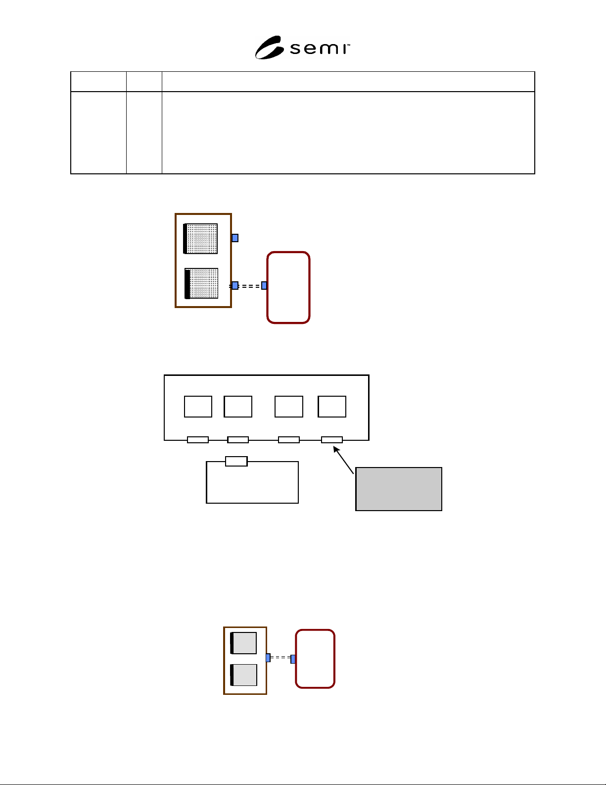
SEMI E84-0305 © SEMI 1999, 2005 10 NOTE 1: This figure shows logical concep t only. Phys ical locatio n is not defi ned by this standard. Figure 6 Common Parallel I/O for Two Load Ports OHS (p assive t ype ) PI/O PI/O ac…
SEMI E84-0305 © SEMI 1999, 2005 9
Signal Name P/A Description
Specifies the load port used for carrier handoff.
One PI/O device per Load Port.
OFF: Not used
One PI/O device per 2 load ports.
ON: Use the right load port for handoff.
OFF: Do not use the right load port for handoff.
Note: This signal is for interbay passive OHS vehicle use only.
AGV / RGV / OHT / OHS(active type)
Passive
Equipment
PI/O
PI/O
Figure 4
One Parallel I/O Interface for Each Load Port
LP4
LP 3LP2LP1
Passive Equipment
PI/O #1 PI/O #2 PI/O #3 PI/O #4
A
GV/RGV/OHT/OHS(active type)
A
t each PI/O
CS_0 is ON
CS_1 is OFF
NOTE 1: This figure shows logical concept only. Physical location is not defined by this standard.
Figure 5
Example of Correspondence of CS_0/CS_1 and Load Ports (Top View) - Single PI/O Controls 1 Load Port
Passive Equipment
PI/O
AGV/RGV/OHT
L
R
SEMI E84-0305 © SEMI 1999, 2005 10
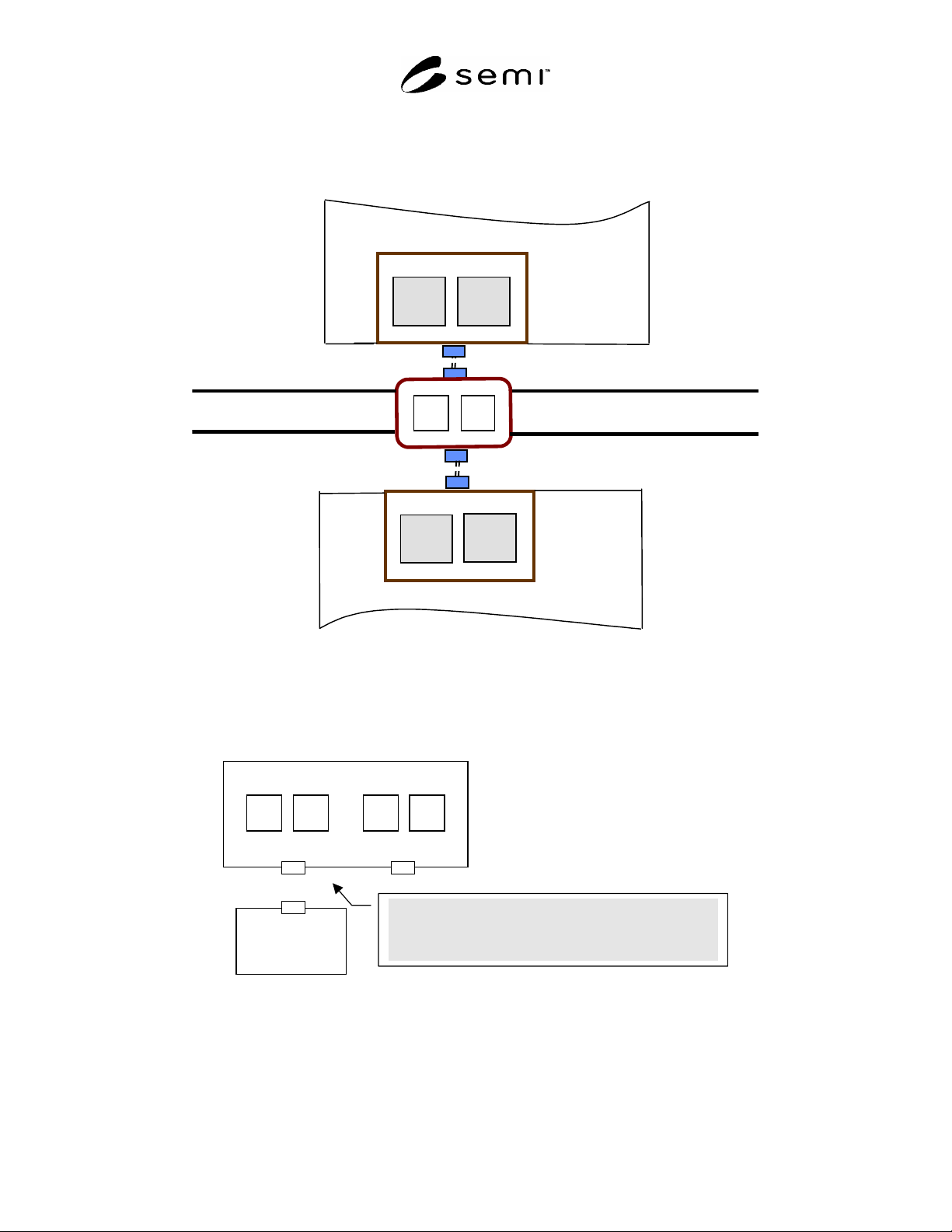
NOTE 1: This figure shows logical concept only. Physical location is not defined by this standard.
Figure 6
Common Parallel I/O for Two Load Ports
OHS (passive type)
PI/O
PI/O
active equipment
Left
Right
Left
Right
STOCKER
STOCKER
NOTE 1: This figure shows the logical concept only. Physical location is not defined by this standard.
NOTE 2: Decide the left side and right side according to the direction of the equipment from the vehicle.
Figure 7
Common Parallel I/O for Two Load Ports (Interbay AMHS Scenario)
LP1 LP3LP2
Passive Equipment
PI/O#1 PI/O#2
LP4
AGV/RGV/OHT
at PI/O#1 CS_0 specifies LP1 and CS_1 specifies LP2.
at PI/O#2 CS_0 specifies LP3 and CS_1 specifies LP4.
NOTE 1: This figure shows logical concept only. Physical location is not defined by this standard.
Figure 8
Example of Correspondence of CS_0/CS_1 and Load Ports (Top View) - Single PI/O Controls 2 Load Ports
SEMI E84-0305 © SEMI 1999, 2005 11
Table 2 Example of the Load Port Specified by CS_0/CS_1 Signal (one PI/O per 2 load ports)
PI/O# CS_0 CS_1 Load Port Comment
1 ON OFF LP1 Single Handoff or Continuous Handoff
1 OFF ON LP2 Single Handoff or Continuous Handoff
1 ON ON LP1 & LP2 Simultaneous Handoff
2 ON OFF LP3 Single Handoff or Continuous Handoff
2 OFF ON LP4 Single Handoff or Continuous Handoff
2 ON ON LP3 & LP4 Simultaneous Handoff
Table 3 Example of the Load Port Specified by CS_0/CS_1 Signal (one PI/O per load port)
PI/O# CS_0 CS_1 Load Port Comment
1 ON OFF LP1
2 ON OFF LP2
3 ON OFF LP3
4 ON OFF LP4
When a PI/O is dedicated to a single load port, CS_0 is always
on, CS_1 is always off.
Table 4 Example of the Load Port Specified by VS_0/VS_1 Signal (One PI/O per 2 load ports)
Left Load Port Right Load Port
VS_0 ON
OFF
×
VS_1 ON
OFF
×
= Select
× = Not Select
= Do not care
6.2 Carrier Handoff Sequences
6.2.1 The signals of the enhanced carrier handoff parallel I/O interface compliant to this specification must follow
these defined sequences. The time diagrams of the carrier handoff sequences are shown in Figures 10–29. Figure 10
is a summary of various handoffs including load/unload and single/simultaneous/continuous handoff sequences.
Figure 11 is a transition model of zones. Each change in signal state is numbered in the time diagrams. These
numbers are for reference only and may not correspond with the handoff steps or signal order requirements in ¶6.2.
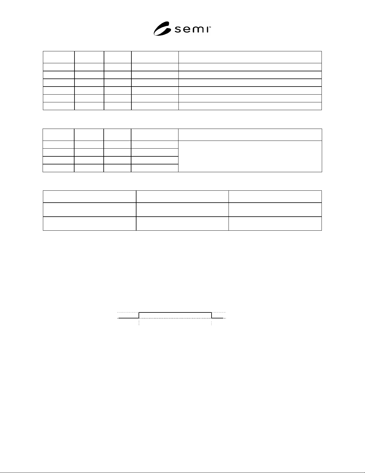
Event A Event B
signal on
signal off
Figure 9
Key for Timing Diagram Signal States
6.2.2 Load/Unload Boundaries
6.2.2.1 Changes in the signal state are shown and described as boundaries to clarify each step during handshake and
transfer as seen in the signal time diagram in Figure 10 and Tables 5 and 6.