semi合集-English.pdf - 第1582页
SEMI E37-0303 © SEMI 1995, 2003 4 5.2 State Descriptions 5.2.1 NOT CONNECTED — The entity is read y to listen for or initiate TCP/IP connections but either has not yet established any connections or all p reviously estab…

SEMI E37-0303 © SEM 1995, 2003 3
unconfirmed service (HSMS) — an HSMS service
requested by sending a message from the initiator to the
responding entity which requires no indication of
completion from the responding entity.
5 HSMS Overview and State Diagram
High-Speed SECS Message Services (HSMS) defines a
communication interface suitable for the exchange of
messages between computers in a semiconductor
factory using a TCP/IP environment. HSMS uses
TCP/IP stream support, which provides reliable two
way simultaneous transmision of streams of contiguous
bytes. It can be used as a replacement for SECS-I
communication as well as other more advanced
communications environments.
The procedure for HSMS communications parallels the
more familiar SECS-I communications it replaces. The
following steps are followed for any communications
(HSMS or otherwise):
1. Obtain a communications link between two
entities. In SECS-I, this is the RS232 wire
physically connecting host and equipment. In
HSMS, the link is a TCP/IP connection obtained by
the standard TCP/IP connect procedure. Note that
the abstract term “entity” is used instead of “host”
or “equipment.” This is because, while HSMS is
used for SECS-I replacement, it has more general
applications as well. In a SECS-I replacement
application, the “host” is an “entity” and the
“equipment” is an “entity.”
2. Establish the application protocol conventions to
be used for exchanging data messages between two
entities. For SECS-I, this step is implicit in the fact
that semiconductor equipment is physically
connected on the two ends of the wire: the protocol
is SECS-II.
In the case of HSMS, the communications link is a
dynamically established TCP/IP connection on a
physical link which may be shared with many other
TCP/IP connections using protocols other than
HSMS or connections using non TCP/IP protocols.
HSMS adds a message exchange (called the Select
procedure) which is used to confirm to both entities
that the particular TCP/IP connection is to be used
exlusively for HSMS communications.
3. Exchange Data. This is the normal intended
purpose of the communications link. In both
SECS-I and HSMS, the procedure is to exchange
SECS-II encoded messages for the control of
semiconductor equipment and/or processes. Data
exchange normally continues until one or both of
the entities are taken off-line for equipment-
specific purposes, such as maintenance.
4. Formally end communications. In SECS-I, there is
no formal requirement here; the equipment to be
taken off-line stops communicating.
In HSMS, a message exchange (either the
“bilateral” Deselect procedure or the “unilateral”
separate procedure) is used for both parties to
confirm that the TCP/IP connection is no longer
needed for HSMS communications.
5. Break the communications link. In SECS-I, this is
done by physically unplugging the host or
equipment from the communications cable, which
only occurs during repair or physical
reconfiguration of the factory network
environment.
In HSMS, since it uses the dynamic connection
environment of TCP/IP, the TCP/IP connection is
logically broken via a release or a disconnect
procedure without any physical disconnect from
the network medium.
Two additional procedures, of a diagnostic nature, are
supported in HSMS, which are generally not required
by a simple SECS-I link or a SECS-I direct
replacement. These follow:
1. Linktest. This procedure provides a simple
confirmation of connection integrity.
2. Reject. Because HSMS is intended to be extended
to protocols other than just SECS-II (by means of
subsidiary standards), it is possible that two entities
can be connected (due to a configuration error)
which use incompatible subsidiary standards. Also,
during initial implementation, incorrect message
types may be sent, or they may be sent out of order
due to software bugs. The reject procedure is used
to indicate such an occurrence.
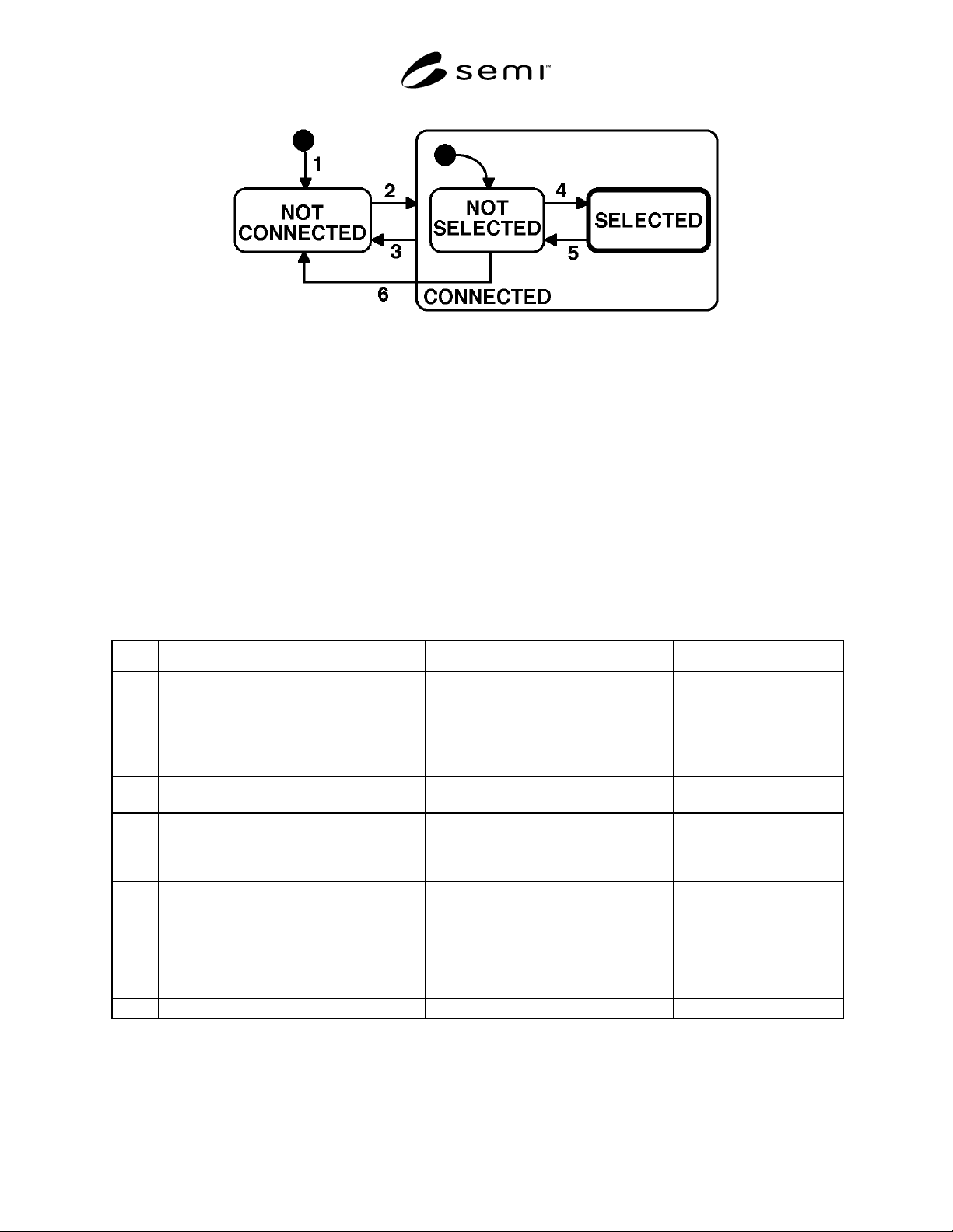
5.1 HSMS Connection State Diagram — The HSMS
state machine is illustrated in the diagram below. The
behavior described in this diagram defines the basic
requirements of HSMS: subsidiary standards may
further extend these or other states.
SEMI E37-0303 © SEMI 1995, 2003 4
5.2 State Descriptions
5.2.1 NOT CONNECTED — The entity is ready to listen for or initiate TCP/IP connections but either has not yet
established any connections or all previously established TCP/IP connections have been terminated.
5.2.2 CONNECTED — A TCP/IP connection has been established. This state has two substates, NOT SELECTED
and SELECTED.
5.2.2.1 NOT SELECTED — A substate of CONNECTED in which no HSMS session has been established or any
previously established HSMS session has ended.
5.2.2.2 SELECTED — A substate of CONNECTED in which at least one HSMS session has been established. This
is the normal “operating” state of HSMS: data messages may be exchanged in this state. It is highlighted by a heavy
outline in the state diagram.
5.3 State Transition Table
Table 1
# Current State Trigger New State Actions Comment
1 ... Local entity-specific
preparation for TCP/IP
communication.
NOT CONNECTED Local entity-specific Action depends on
connection procedure to be
used: active or passive.
2 NOTCONNECTED A TCP/IP connection is
established for HSMS
communication.
CONNECTED -
NOT SELECTED
Local entity-specific none
3 CONNECTED Breaking of TCP
connection.
NOT CONNECTED Local entity-specific See Section 6.4.
4 NOT SELECTED Successful completion of
HSMS Select Procedure.
SELECTED Local entity-specific HSMS communication is
now fully established: data
message exchange is
permitted.
5 SELECTED Successful completion of
HSMS Deselect or
Separate.
NOT SELECTED Local entity-specific This transition normally
indicates the end of HSMS
communication and so an
entity would immediately
proceed to break the TCP/IP
connection (transition 3
above).
6 NOT SELECTED T7 Connection Timeout. NOT CORRECTED Local entity-specific per Section 9.2.2
SEMI E37-0303 © SEM 1995, 2003 5
6 Use of TCP/IP
6.1 TCP/IP API — The specification of a required TCP
Application Program Interface (API) for use in
implementations is outside the scope of HSMS. A given
HSMS implementation may use any TCP/IP API —
sockets, TLI (Transport Layer Interface), etc. —
appropriate to the intended hardware and software
platform, as long as it provides interoperable TCP/IP
streams protocol on the network.
The appendix contains examples of the TCP/IP
procedures referenced in this standard and sample
scenarios using both the TLI (POSIX standard 1003.12)
and the popular BSD socket model for TCP/IP
communication.
6.2 TCP/IP Network Addressing Conventions
6.2.1 IP Addresses — Each physical TCP/IP
connection to a given Local Area Network (LAN) must
have a unique IP Address. IP Addresses must be
assignable at installation time, and an HSMS
implementation cannot select a fixed IP Address. A
typical IP Address is 192.9.200.1.
IP imposes restrictions on these numbers which are
outside the scope of the HSMS protocol. Consult
Section 2.3 of RFC 791, Internet Protocol (IP) in
Section 3.
6.2.2 TCP Port Numbers — A TCP Port Number can
be considered as an extension of the IP Address.
HSMS implementations should allow configuring TCP
Port to the full range of the TCP/IP implementation
used. A typical TCP Port Number is 5000.
Conventions have been established for selecting TCP
Port Numbers which are outside the scope of the HSMS
protocol. Consult RFC 793, Transmission Control
Protocol (TCP) in Section 3.
6.3 Establishing a TCP/IP Connection
6.3.1 Connect Modes — The procedures for
establishing a TCP/IP connection are defined in RFC
793. However, not all the procedures defined by RFC
793 are supported by commonly available APIs. In
particular, while RFC 793 permits both entities to
initiate the connection simultaneously, this feature is
rarely supported in available
APIs. Therefore, HSMS restricts an entity to one of the
following modes:
• Passive Mode. The Passive mode is used when the
local entity listens for and accepts a connect
procedure initiated by the Remote Entity.
• Active Mode. The Active mode is used when the
connect procedure is initiated by the Local Entity.
The appendix provides an example of how an entity
may operate alternately in the active and passive modes
to achieve greater flexibility in establishing
communications.
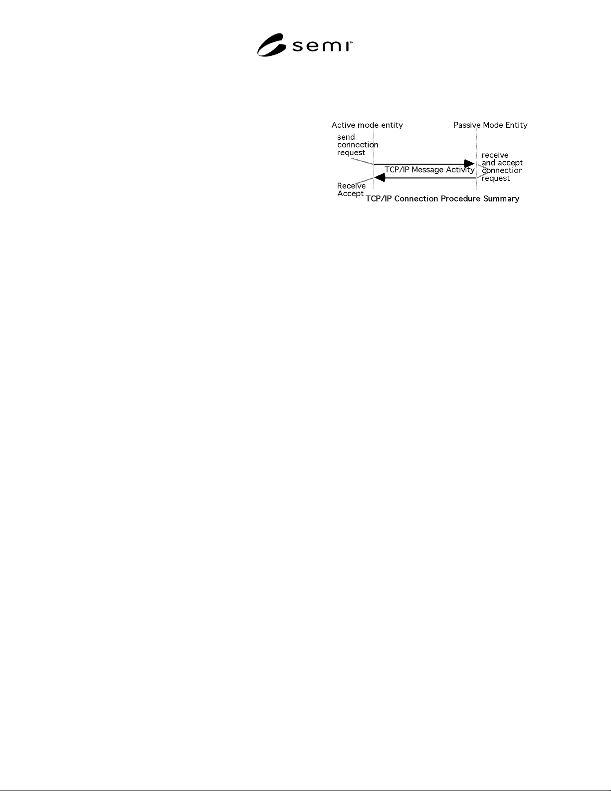
6.3.2 Passive Mode Connect Procedure — The
procedure followed by the Passive Local Entity is
defined in RFC 793. It is summarized as follows:
1. Obtain a connection endpoint and bind it to a
published port.
2. Listen for an incoming connect request to the
published port from a remote entity.
3. Upon receipt of a connect request, acknowledge it
and indicate acceptance of the connection. At this
point, the connect procedure has completed
successfully, and the CONNECTED state is
entered (Section 5).
These procedures are carried out through the API of the
local entity' s implementation of TCP/IP. The
appendices provide the API-specific procedures for the
above steps using both TLI and BSD.
NOTE: A failure may occur during the above steps. The
reason for failure may be local entity-specific or may be due
to a lack of any connect request after a local entity-specific
timeout. The action to be taken (for example: return to step 1
to retry) is a local entity-specific issue.
NOTE: See Section 9, Special Considerations, for issues
relating to multiple connection requests to the same passive
mode entity.
6.3.3 Active Mode Connect Procedure — The
procedure followed by the Active Local Entity is
defined in RFC 793. It is summarized as follows:
1. Obtain a connection endpoint.
2. Initiate a connection to the published port of a
passive mode remote entity.
3. Wait for the receipt of the acknowledge and the
acceptance of the connect request from the remote
entity. Receipt of the acceptance from the remote