semi合集-English.pdf - 第2112页
SEMI E54.14-0305 © SEMI 2005 6 6.4 Data Link Layer — Layer 2 6.4.1 Data Transfer 6.4.1.1 The Data Link Layer provides the functions for sending a nd receiving data over the network. Protocol Data Units (PDU) are packaged…
SEMI E54.14-0305 © SEMI 2005 5
NOTE 2: Within a modular device, a slot typically addresses a physical module. Within compact devices, a slot typically
addresses a logical function or virtual module.
5.4.21 slot related diagnosis — information dedicated to modules for maintenance purpose.
5.4.22 submodule — hardware or logical component of a module.
5.4.23 subslot — address of a structural unit within a slot.
NOTE 3: A subslot may address a physical interface for submodules within a module. Generally, a subslot is a second level to
structure data within a device.
5.4.24 vendor ident number — central administrative number assigned by the PNO.
6 Communication Protocol High Level Structure
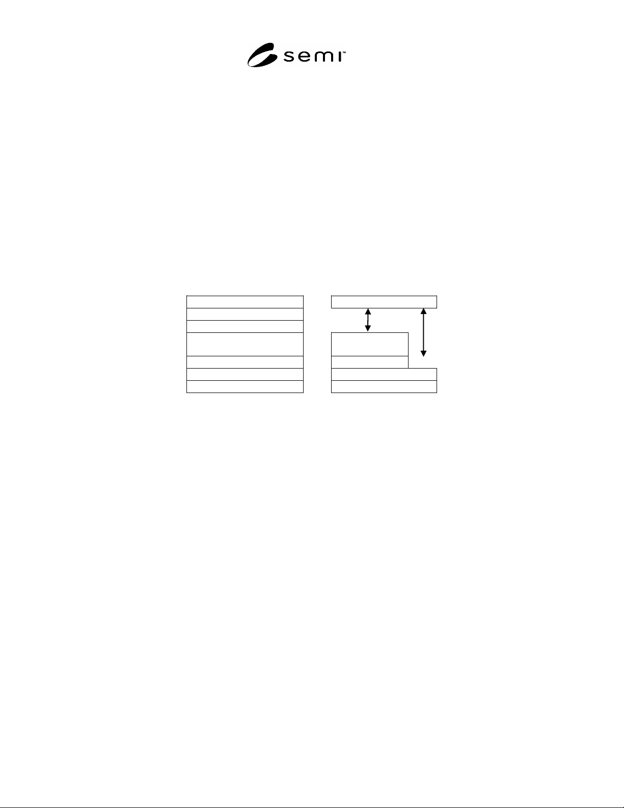
6.1 The PROFINET IO protocol constitutes a collapsed form of the OSI seven layer architecture. PROFINET IO
uses physical, data link, network, transport, and application layers of the Reference Model. For real time
communication a three layer approach with physical, data link and application is specified. This section has been
formatted to be aligned with the Basic Reference Model for OSI. Figure 1 gives an overview of the architecture.
OSI Reference Model NCS Model
Application Layer Application Layer
Presentation Layer
Session Layer
Transport Layer Transport
Layer
Network Layer Network Layer
Data Link Layer Data Link Layer
Physical Layer Physical Layer
Figure 1
Layering of PROFINET in Relation to OSI
6.2 General Behavior
6.2.1 In a typical remote I/O configuration, single IO controller architectures are used to optimize response times.
In lower speed applications, multi IO controller architectures are also possible.
6.2.2 Message transfer is organized in cycles. A message cycle mainly consists of a set of Output Data Frames of
the IO controller and a set of Input Data Frames of several IO devices. Every Output Data Frame is associated to an
Input Data Frame. The monitoring of an IO application relationship is done by the receiver of that frames.
6.2.3 A brief description of the PROFINET protocol as it relates to the ISO 7498 OSI model follows in the sections
below. For protocol efficiency, PROFINET does not define layers 3 to 7 for cyclic IO data transfer and alarms.
Layer 7 is the interface between the Application Process and the communication stack.
NOTE 4: The information contained in this section is for reference only. It in no way represents specifications for PROFINET.
See related documentation for these specifications.
6.3 Physical Layer — Layer 1
6.3.1 The Physical Layer of IEEE 802.3 is adopted. There are two recommendations specified for the Physical
Layer (PHY): twisted pair (100 Base TX) and optical (100 Base FX) in PROFINET. See IEEE 802.3 standard for
more information about these options. More Details are specified in the PROFINET Installation Guideline. If an
accepted physical standard other than IEEE 802.3 is being used it has be clearly specified in the product
documentation.

SEMI E54.14-0305 © SEMI 2005 6
6.4 Data Link Layer — Layer 2
6.4.1 Data Transfer
6.4.1.1 The Data Link Layer provides the functions for sending and receiving data over the network. Protocol Data
Units (PDU) are packaged, delivered, and checked. Checks are used to guard against Line Protocol Errors (e.g.,
frame, overrun, and coding violations). IEEE 802.3 Data Link MAC sublayer is the preferred Data link technology
of PROFINET. If an accepted data link standard other than IEEE 802.3 is being used it has to be clearly specified in
the product documentation.
6.4.1.2 A PDU is restricted to 1500 bytes. A protocol overhead of 28 Bytes is needed for addressing, error
detection and protocol selection.
6.4.2 Conveyance of Data
6.4.2.1 In IEEE 802 networks bridges (switches) are used to transport data. These bridge functions are defined in
IEEE 802.1D and IEEE 802.1Q (priority options). Real time extensions can be used to enhance performance and
availability of bridged networks.
6.5 Network Layer — Layer 3
6.5.1 While real time data transfer uses a protocol with no network layer, all other services are using IP (Internet
Protocol) as network layer.
6.6 Transport Layer — Layer 4
6.6.1 All non-real time services are using UDP (User Datagram Protocol) as transport layer.
6.7 Session Layer — Layer 5
6.7.1 There is no distinct Session Layer in this CDM.
6.8 Presentation Layer — Layer 6
6.8.1 There is no distinct Presentation Layer in this CDM. The Encoding is part of the application layer.
6.9 Application Layer — Layer 7
6.9.1 The PROFINET IO application layer is structured in a so called service definition and protocol specification.
The service definition uses an object orientated approach and specifies the services for remote access and local
functions together with their objects (the ASE is a class definition of these objects). The protocol specification
includes both coding and state machines.
6.9.2 Service Definition
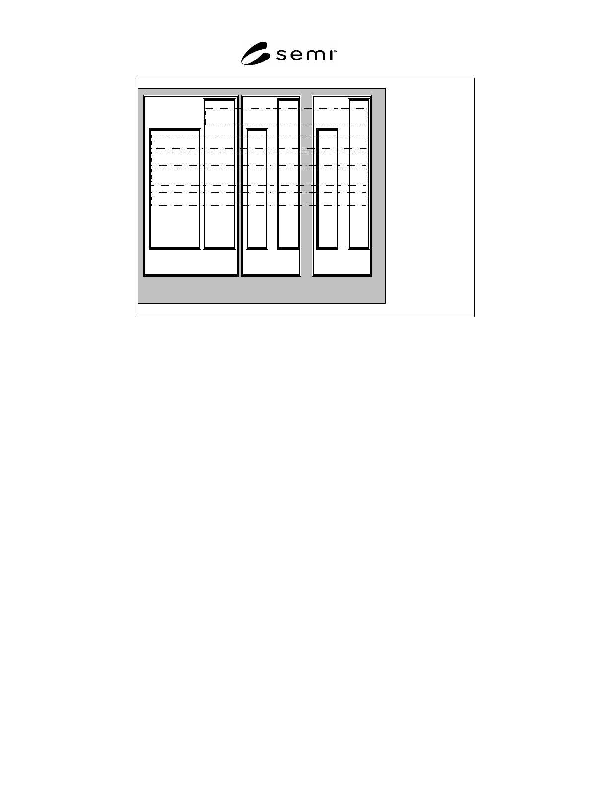
6.9.2.1 Application layer services are structured to reflect the needs of flexible configurable automation devices. A
Device consists of a set of modules that are placed in slots (see Figure 2). Modules are addressed uniquely by the
slot number. The module view can be a hardware oriented or reflects the software structure of the IO Device.
6.9.2.2 Each module contains submodules that contain objects of different classes. Submodules are the addresses of
the submodules.
6.9.2.3 Slot 0 is used to address the IO Device itself. Subslot 0 represents the module and contains no IO Data.
The other object classes can have instances scattered over the modules and their submodules addressed by slots and
their subslots respectively. Each submodule (except submodule 0) can contain IO Data, Context parameter,
Diagnosis information, Record Data and Alarms. Record Data is a generic class which can contain different
application specific parameters accessible by read and write services. There is a set of identification and
maintenance parameters defined in a PROFIBUS Guideline that are mandatory within PROFINET.
SEMI E54.14-0305 © SEMI 2005 7
IO device
Sub
slot
0
Sub
slot
m
...
Slot0
Slot 1 carries
Module x
Sub
slot
0
Sub
slot
m
...
Record Data
Diagnosis
Alarm
IO Data
Subslot 0
Sub
slot
m
Context
Slot n carries
Module y
Figure 2
Device Model
6.9.2.4 Object classes are defined for:
IO Data for periodic reporting,
Context for configuration,
Diagnosis for event collection,
Record Data for polled access, and
Alarms for asynchronous event reporting.
A set of services are defined for these object classes.
6.9.2.5 IO Data are handled mainly by buffered services which allow decoupling between application and
communication. Client/Server service structure (request/response) is used for Context for configuration, Diagnosis
for event collection, Record Data for polled access and Alarms for asynchronous event reporting.
6.9.2.6 Cyclic functionalities offered in PROFINET IO:
exchange of IO data with related IO devices
6.9.2.7 Acyclic functionalities offered in PROFINET IO:
read diagnosis from IO devices
configuration of IO devices
write parameter data to IO devices (startup or application parameter)
treatment of configuration and diagnosis requests of an engineering device
initiate connections to IO devices by means of context management
acyclic access to record data of IO devices
treatment of alarms from IO devices