semi合集-English.pdf - 第2377页
SEMI E84-0305 © SEMI 1999, 2005 21 L_REQ (P->A) READY (P->A) HO_AVBL (P->A) ES (P->A) CS_0 (A->P) CS_1 (A->P) VALID (A->P) TR_REQ (A->P) BUSY (A->P) COMPT (A->P) CS is Specified Carrier is D…
SEMI E84-0305 © SEMI 1999, 2005 20
6.2.6 Continuous Handoff Sequence
6.2.6.1 This specification defines the capability to control continuous handoff. Continuous handoff is the handoff
operation in which the active equipment transfers two or more carriers sequentially and continuously in a carrier
transfer operation. Some types of AMHS equipment are able to handoff more than two carriers in a transfer
operation. This capability can be applied to increase the performance of the transfer.
6.2.6.2 When the passive equipment has a door in front of the load port, the door on passive equipment must be
opened before the carrier handoff starts by the active equipment. It is redundant to open and close the door for a
carrier handoff when two or more carriers are transferred. Therefore, the door shall be kept open during the carrier
transfer operation. Continuous handoff is applied to the transfer operation to avoid redundant operations.
6.2.6.3
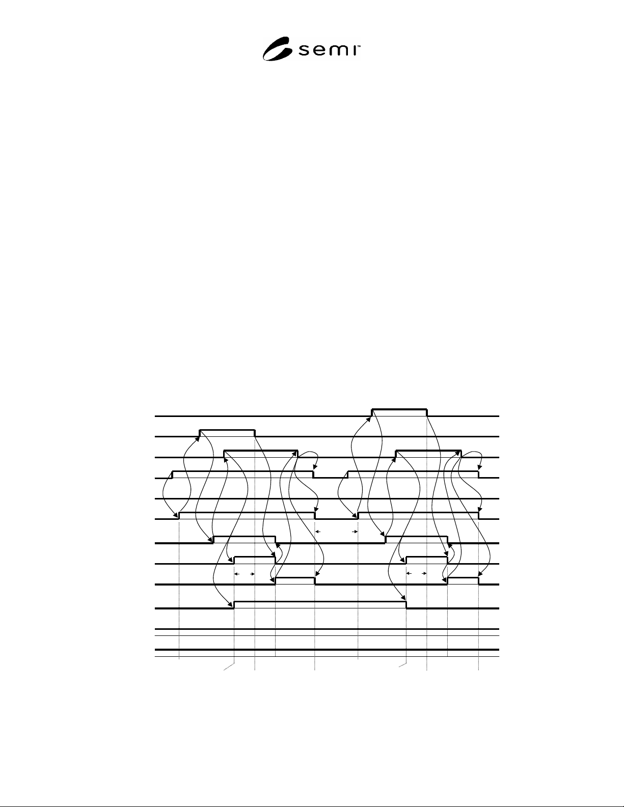
Continuous handoff sequence for handoffs at a load port (Unload -> Load): The example time diagram for
continuous handoff is shown in Figure 18. This example shows the sequence of unload and load operations
performed continuously at the load port. Each sequence in the continuous handoff is the combination of the single
handoff sequence. In addition, the CONT signal is used to indicate a continuous handoff. In the sequence shown in
Figure 10, the carrier on the load port is unloaded first, and a new carrier is loaded on the load port. The CONT
signal is turned ON at the time of active equipment BUSY ON of the first handoff to indicate that the handoff is
continuous. In successive load sequences, the same load port number (CS_0 in this example) is specified to use the
same load port. In this example, there are no more carriers that are to be transferred after the second load sequence,
therefore the active equipment turns the CONT signal OFF when the BUSY signal is turned ON in the second
handoff to indicate the continuous handoff is complete.
6.2.6.4
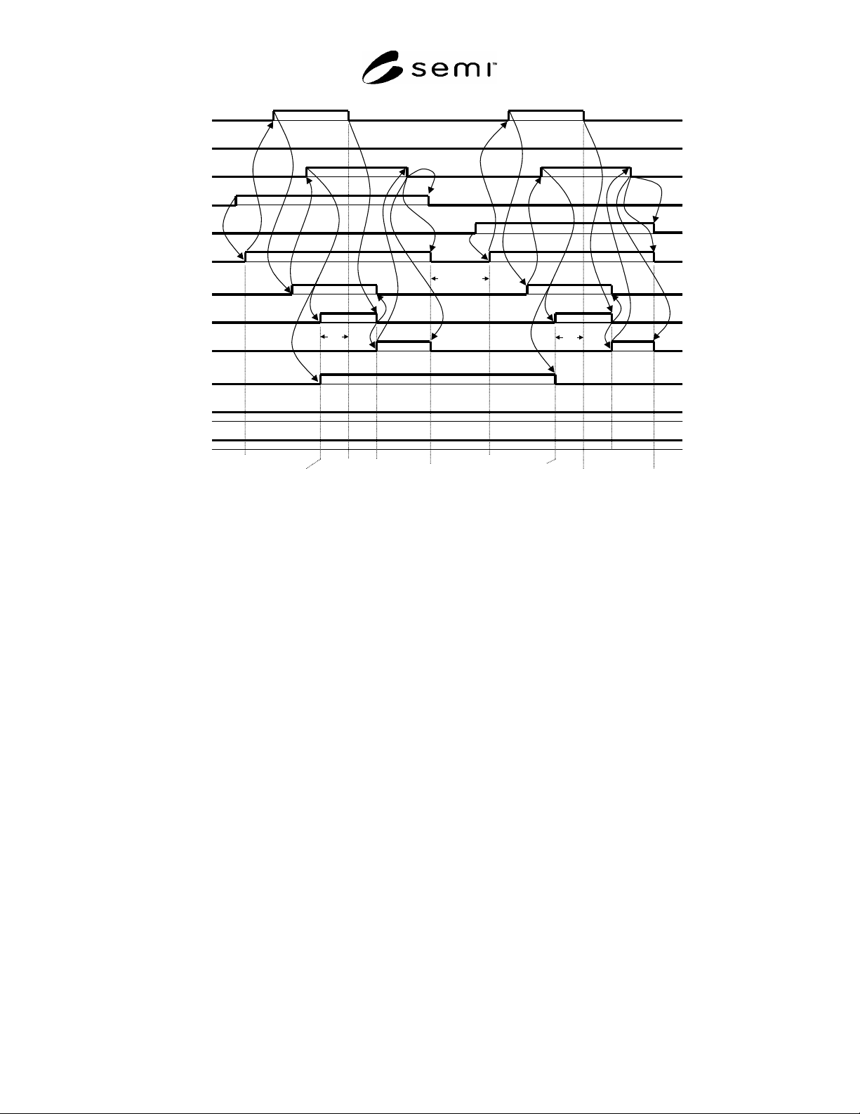
Continuous handoff sequence for handoffs at different load ports (Load -> Load): The example time
diagram for continuous handoff on the different load ports is shown in Figure 19. In this example, the active
equipment first transfers a carrier to the load port corresponding to CS_0, then another carrier is transferred to the
load port corresponding to CS_1. In this example, the sequence is the same as that of the continuous handoff
(handoff at a load port: Unload -> Load) shown in section above except for the specification of the load ports.
L_REQ
(P->A)
READY
(P->A)
HO_AVBL
(P->A)
ES
(P->A)
CS_0
(A->P)
CS_1
(A->P)
VALID
(A->P)
TR_REQ
(A->P)
BUSY
(A->P)
COMPT
(A->P)
CS is
Specified
Carrier is
Detected
Transfer is
Completed
Release CS
is Specified
Transfer
Start
U_REQ
(P->A)
CONT
(A->P)
CS is
Specified
Carrier is
Detected
Transfer is
Com
p
leted
Release CS
is Specified
Transfer
Start
TD0
TD0
TA1
TA1
TA2
TA2
TA3
TA
TP1TP1
TP2TP2
TP3TP3
TP4
TP4
TP5 TP5
1
2
3
5
8
12
9
6
4
11
10
14
13
15
7
16
17
18
20
23
27
24
21
19
26
25
30
28
29
22
step numbers
are for
reference only
TP6 / TD1
Figure 18
Signal Time Diagram for Continuous Handoff (UNLOAD and LOAD)
SEMI E84-0305 © SEMI 1999, 2005 21
L_REQ
(P->A)
READY
(P->A)
HO_AVBL
(P->A)
ES
(P->A)
CS_0
(A->P)
CS_1
(A->P)
VALID
(A->P)
TR_REQ
(A->P)
BUSY
(A->P)
COMPT
(A->P)
CS is
Specified
Carrier is
Detected
Transfer is
Completed
Release CS
is Specified
Transfer
Start
U_REQ
(P->A)
CONT
(A->P)
CS is
Specified
Carrier is
Detected
Transfer is
Completed
Release CS
is Specified
Transfer
Start
TD0
TD0
TA1
TA1
TA2
TA2
TA3
TA3
TP1
TP1
TP2
TP2
TP3
TP3
TP4
TP4
TP5
TP5
step numbers
are for
reference only
1
2
3
5
8
12
9
6
4
11
10
14
13
15
7
16
17
18
20
23
27
24
21
19
26
25
30
28
29
22
TP6 / TD1
Figure 19
Signal Time Diagram for Continuous Handoff (LOAD and LOAD)
6.2.7 Handoff Available Signal Operation Sequence (HO_AVBL)
6.2.7.1 Example time diagrams for the HO_AVBL signal are shown in Figures 20 through 26. The HO_AVBL
signal is ON during passive equipment normal operations and shall be turned OFF when the passive equipment
detects an exception for the handoff. The active equipment is informed of the exception condition by the HO_AVBL
signal. The HO_AVBL signal may be turned OFF independently of the other SEMI E84 signals, prior to or during
the handoff. The active equipment is expected to confirm the HO_AVBL signal in the following periods:
a)
From the time at which the VALID signal is turned ON to the time at which the L_REQ or U_REQ signal is
turned ON.
b)
From the time at which the TR_REQ signal is turned ON to the time at which the READY signal is turned
ON.
6.2.7.2
Figures 20 through 23 are the time diagrams to explain situation a) in the section above and show examples
of potential HO_AVBL signal activity. The active equipment stops the handoff when it detects that the HO_AVBL
signal is turned OFF by the passive equipment. The active equipment turns the VALID signal OFF to close the
handshake (CS_0 and CS_1 signals must be set to OFF at this time). The passive equipment turns the HO_AVBL
signal ON after the VALID signal is turned to OFF (L_REQ or U_REQ must be set to OFF).
6.2.7.3
Figures 24 through 26 are the time diagrams to explain situation b) in the section above and show examples
of potential HO_AVBL signal activity. The active equipment stops the handoff when it detects that the HO_AVBL
signal is turned OFF by the passive equipment. The active equipment turns the VALID signal OFF to close the
handshake (CS_0, CS_1, and TR_REQ signals must be set to OFF). The passive equipment turns the HO_AVBL
signal ON after the VALID signal is turned to OFF (L_REQ or U_REQ must be set to OFF).
6.2.8 Handoff Available Signal Operation Sequence (for interbay passive OHS and Stocker)
6.2.8.1 Example time diagrams for the HO_AVBL signal are shown in Figures 27 through 29. The HO_AVBL
signal is ON during passive OHS normal operations and shall be turned OFF when the passive OHS detects an
exception for the handoff. The active stocker is informed of the exception condition by the HO_AVBL signal. The
SEMI E84-0305 © SEMI 1999, 2005 22
HO_AVBL signal may be turned OFF independently of the other SEMI E84 signals, prior to or during the handoff.
The active stocker is expected to confirm the HO_AVBL signal in the following period:
a) From the time at which the TR_REQ signal is turned ON to the time at which the READY signal is turned ON.
6.2.8.2 Figures 27 through 29 are diagrams explaining the above item a) and showing examples of potential
HO_AVBL signal activity. The active stocker stops transferring when the active stocker detects that the HO_AVBL
signal has been turned OFF by the passive OHS. By turning off the AM_AVBL signal, the active Stocker closes the
transfer sequence. In such a case, the TR_REQ signal must go OFF as the transfer sequence has ended. Also, the
passive OHS must turn OFF the VS_0 and VS_1 signals. Next, the passive OHS must turn ON the HO_AVBL
signal after the VA signal has gone OFF (the L_REQ or U_REQ must be set OFF).
L_REQ
(P->A)
READY
(P->A)
HO_AVBL
(P->A)
ES
(P->A)
CS_0
(A->P)
CS_1
(A->P)
VALID
(A->P)
TR_REQ
(A->P)
BUSY
(A->P)
COMPT
(A->P)
HO_AVBL is
Confirmed
OFF
End of
Handshake
CONT
(A->P)
TD0
step numbers are
for reference only
1
2
6
3
4
5
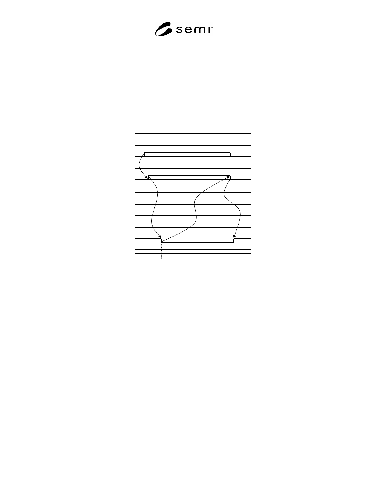
NOTE 1: The HO_AVBL signal turns OFF while the active equipment is confirming the signal in step 3.
Figure 20
Example of Handoff Available Signal