semi合集-English.pdf - 第6040页
SEMI G4-0302 © SEMI 1982, 2002 4 5.6 Flatness Test Piece Straight Edge 1000 mm Length of Strip 1200 mm Camber (max. ) Figure 1 Cam ber 5.6.1 Coil Set (Longit udinal Cur l) 5.6.1.1 Coil set shall be measured by attachin g…
SEMI G4-0302 © SEMI 1982, 2002 3
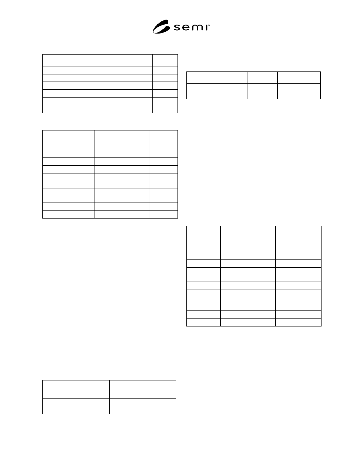
Table 4
Width Thickness Tolerance
under 15 mm to 55 mm 0.1 mm to under 0.3 mm ± 0.05 mm
0.3 mm to under 1.0 mm ± 0.08 mm
1.0 mm to 2.0 mm ± 0.15 mm
over 55 mm to 100 mm 0.1 mm to under 0.3 mm ± 0.08 mm
0.3 mm to under 1.0 mm ± 0.12 mm
1.0 mm to 2.0 mm ± 0.15 mm
Table 5
Width Thickness Tolerance
under 15 mm over 0.1 mm to 0.3 mm ± 0.05 mm
over 0.3 mm to 1.0 mm ± 0.08 mm
over 1.0 mm to 2.0 mm ± 0.15 mm
15 mm to 55 mm over 0.1 mm to 0.3 mm ± 0.05 mm
over 0.3 mm to 1.0 mm ± 0.08 mm
over 1.0 mm to 2.0 mm ± 0.15 mm
Over 55 mm to 100
mm
over 0.1 mm to 0.3 mm ± 0.08 mm
over 0.3 mm to 1.0 mm ± 0.12 mm
over 1.0 mm to 2.0 mm ± 0.15 mm
* Table 5 is used in Europe.
5.4 Surface Finish
5.4.1 The material shall be commercially free of
surface imperfections such as pits, nicks, dents, gouges,
scratches, laminations, or inclusions.
5.4.2 The surface roughness of both sides shall be
measured perpendicular to the direction of rolling and
indicated as the arithmetic average height (R
a
) and the
maximum peak-to-valley roughness height (R
max
).
5.4.2.1 Measurement and designations of surface
roughness shall conform to appropriate area standards
based on country or area of material origin.
5.4.2.1.1 Europe ISO 4287 Part 1
5.4.2.1.2 Japan JIS B0601
5.4.2.1.3 United States ANSI/ASME B46.1
5.4.2.2 Conditions for the measurement are shown in
Table 6.
Table 6
Radius of Diamond
Stylus: Less than 5mm
(Record Actual Size)
Cut Off: 0.8 mm
Stroke: 4 mm
5.4.2.3 Maximum acceptable values for surface
roughness are shown in Table 7.
Table 7
Thickness R
a
R
max
0.1 mm to under 0.3 mm 0.15 µm 1.0 µm (1.5 µm)
0.3 mm to 2 mm 0.20 µm 1.5 µm (2.0 µm)
* Values in parentheses are used in Europe.
5.5 Camber (Edgewise Curvature)
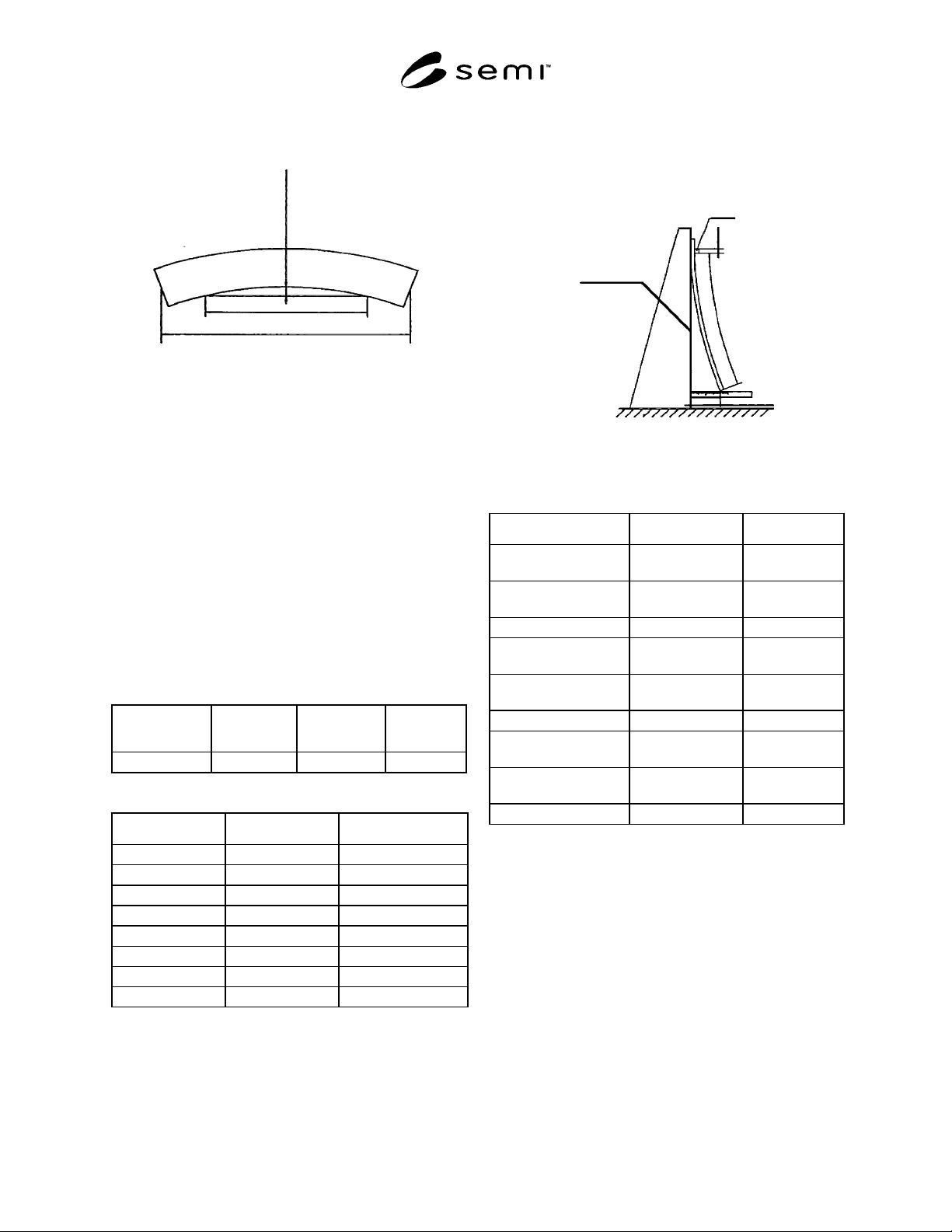
5.5.1 Camber is measured by placing a length of strip
on a flat surface against the edge of a straight edge, as
shown in Figure 1. The straight edge shall be of
sufficient length to equal or exceed the length
traditionally used in the area or country of origin of the
material. The largest amount of separation of the strip
sample from the straight edge shall be measured.
Extreme care must be exercised with this test to ensure
that the sample illustrates a uniform camber (no reverse
curvature should be present in the sample), and also that
it is not bent or kinked, as this could result in a grossly
inaccurate measurement. The maximum camber per
length allowable are shown in Table 8.
Table 8
Width
Thickness
Max camber
allowed in 1 meter
Under 15 mm 0.1 mm to under 0.3 mm 1.8 mm (2.0 mm)
0.3 mm to under 1.0 mm 2.2 mm (2.5 mm)
1.0 mm to 2.0 mm 4.0 mm
15 mm to
55 mm
0.1 mm to under 0.3 mm 1.3 mm
0.3 mm to under 1.0 mm 2.0 mm
1.0 mm to 2.0 mm 3.0 mm
Over 55 mm
to 100 mm
0.1 mm to under 0.3 mm 1.0 mm
0.3 mm to under 1.0 mm 1.5 mm
1.0 mm to 2.0 mm 2.5 mm
SEMI G4-0302 © SEMI 1982, 2002 4
5.6 Flatness
Test Piece
Straight Edge 1000 mm
Length of Strip 1200 mm
Camber (max.)
Figure 1
Camber
5.6.1 Coil Set (Longitudinal Curl)
5.6.1.1 Coil set shall be measured by attaching a length
of strip, appropriate to the country or area of material
origin, to a flat vertical surface as shown in Figure 2.
The attachment shall be with a rigid block, wider than
the strip. The block shall be so rigid as to ensure
complete contact of the strip with the vertical surface.
The distance between the flat surface and the free-
hanging end of the strip (that is positioned for
maximum distance from the flat vertical surface) shall
be measured. The coil set shall be uniformly in the
direction of coiling. Lengths shall be appropriate to the
country or area of material origin. Maximum coil set for
appropriate lengths are shown in Tables 9 and 10.
Table 9
Inside Diame
ter of Coil
Thickness
Width
Max Coil
Set in 1 m
400 mm under 0.3 mm under 100 mm 100 mm
Table 10
Thickness Width Max Coil Set in 0.3 m
Under 0.3 mm up to 15 mm 60 mm
over 15 to 24 mm 50 mm
over 24 to 55 mm 45 mm
over 55 to 100 mm 40 mm
0.3 mm to 0.5 mm up to 15 mm 70 mm
over 15 to 24 mm 60 mm
over 24 to 55 mm 55 mm
over 55 to 100 mm 50 mm
* Table 10 is used in Europe.
5.6.2 Crossbow (Dish)
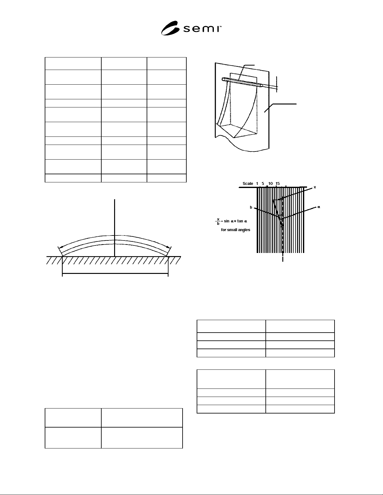
5.6.2.1 Crossbow shall be measured across the width of
the strip, as shown in Figure 3. Burrs shall be removed
or burr height excluded from this measurement.
Crossbow shall be measured with a tool maker’s
microscope or equivalent. Crossbow maxima are listed
in Tables 11 and 12.
Flat Vertical
Surface
Block
Coil Set
20 mm
1000 mm
Figure 2
Coil Set
Table 11
Width Thickness Crossbow Limit
under 15 mm 0.1 mm to under
0.3 mm
0.5% of width
0.3 mm to under
1.0 mm
1.0% of width
1.0 mm to 2.0 mm 1.5% of width
15 mm to 55 mm 0.1 mm to under
0.3 mm
0.5% of width
0.3 mm to under
1.0 mm
0.5% of width
1.0 mm to 2.0 mm 0.5% of width
over 55 mm to 100 mm 0.1 mm to under
0.3 mm
0.4% of width
0.3 mm to under
1.0 mm
0.4% of width
1.0 mm to 2.0 mm 0.4% of width
SEMI G4-0302 © SEMI 1982, 2002 5
Table 12
Width Thickness Crossbow Limit
from 15 mm to 24 mm 0.1 mm to under
0.3 mm
0.10 mm
0.3 mm to under
1.0 mm
0.15 mm
1.0 mm to 2.0 mm 0.20 mm
over 24 mm to 55 mm 0.1 mm to under
0.3 mm
0.15 mm
0.3 mm to under
1.0 mm
0.20 mm
1.0 mm to 2.0 mm 0.25 mm
over 55 mm to 100 mm 0.1 mm to under
0.3 mm
0.25 mm
0.3 mm to under
1.0 mm
0.30 mm
1.0 mm to 2.0 mm 0.35 mm
* Table 12 is used in Europe.
Crossbow (max)
Maximum depth, d
Entire width, w
Seeming width, w
s
AB
Figure 3
Crossbow
5.6.3 Twist
5.6.3.1 Twist shall be measured in a fashion similar to
coil set, as shown in Figure 4A or Figure 4B. A length
of strip, appropriate to the country or area of material
origin, shall be attached at one end to a flat vertical
surface. The attachment shall be with a rigid block,
wider than the strip. The block shall be so rigid as to
ensure complete contact of the strip with the vertical
surface. At the free end of the strip, the distance from
the vertical surface and both edges of the free strip end
shall be measured. The maximum difference in these
dimensions is shown in Table 13.
Table 13
Thickness Twist Maximum (Difference in
Edge Distance)
0.1 mm to 0.5 mm Width × 0.2823 for
1000mm (Width × 0.2823
for 300mm)
* Value in parentheses is used in Europe.
Block
Flat Vert
Surface
20 mm
1000 mm
Figure 4
Twist Test
Figure 4B
Twist Test
5.7 Burrs
5.7.1 Edge burrs shall not exceed the values in Table
14 and 15. As shown in Figure 5, a-b shall be measured.
Table 14
Thickness Maximum Allowed Edge Burr
0.1 mm to under 0.3 mm Thickness x 10%
0.3 mm to under 1.0 mm Thickness x 7%
1.0 mm to under 2.0 mm Thickness x 5%
Table 15
Thickness
Maximum Allowed Edge
Burr Height
0.1 mm to 0.3 mm 0.02 mm
Over 0.3 mm to 1.0 mm 0.03 mm
Over 1.0 mm to 2.0 mm 0.04 mm
* Table 15 is used in Europe.