semi合集-English.pdf - 第6951页
SEMI S8-0705 © SEMI 1995, 2005 48 Section 7: Maintainability and Serviceability Section Indicator Figure 7.1 Minimum lighting level in routine maintenance areas is required where the operator has to read informat ion, us…
SEMI S8-0705 © SEMI 1995, 2005 47
Section 6: Handle Design
Section Indicator Figure
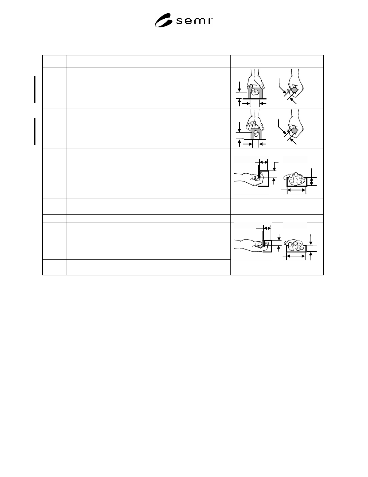
6.7.3 Enclosed handle, two fingers
Width (W): minimum 60 mm (2.5 in.)
Depth (D): minimum 38 mm (1.5 in.)
Diameter (d): minimum 6.3 mm (0.25 in.)
Force maximum: 51 N (11.5 lbf)
Width
Depth
Diameter
6.7.4 Enclosed handle, one finger
Width (W): minimum 38 mm (1.5 in.)
Depth (D): minimum 38 mm (1.5 in.)
Diameter (d): minimum 3.2 mm (0.13 in.)
Force: maximum 27 N (6 lbf)
Width
Depth
Diameter
6.8
Hook Grasp Handle
6.8.1
Hook Grasp Handle (4 fingers)
Opening length (L): minimum 90 mm (3.5 in.)
Opening width (W): minimum 38 mm (1.5 in.)
Depth (d): minimum 50 mm (2.0 in.)
Lip length (l): minimum 50 mm (2.0 in.)
Opening
Width
Opening Length
Lip
Length
Opening
Depth
6.8.2
Hook grasp handle pull force (four fingers)
Pull force: maximum 80 N (18.0 lbf)
6.9
Finger Pull Handle
6.9.1
Finger pull Handle (4 fingers)
Opening length (L): minimum 90 mm (3.5 in.)
Opening width (W): minimum 25 mm (1.0 in.)
Depth (d): minimum 19mm (0.75 in.)
Lip length (l): minimum 19mm (0.75 in.)
6.9.2
Finger pull handles pull force (four fingers)
Pull force: maximum 9.8 N (2.2 lbf)
Opening
Width
Opening Length
Lip
Length
Opening
Depth
SEMI S8-0705 © SEMI 1995, 2005 48
Section 7: Maintainability and Serviceability
Section Indicator Figure
7.1 Minimum lighting level in routine maintenance areas is required where
the operator has to read information, use a hand tool, or make a
connection. This provision can be met by providing integral lighting or
portable lighting which can be temporarily attached such that it does not
have to be hand held.
Acceptance criterion: minimum 300 lux (30 fc)
7.2 Full Body Clearance
NOTE A: Forward horizontal distances are measured away from the
equipment or obstruction for body clearance in a given
posture.
NOTE B: Clearances should be provided based on the nature of the
tasks performed in the designated area.
NOTE C: When determining the appropriate working space required
for a given task, first define the working height. Once this is
known, determine the posture(s) associated with the working
height and use Sections 7.2.1–7.2.9 to determine the
minimum working area for that posture.
NOTE D: Minimum working heights are used to determine postures for
sustained activities (tasks which take longer than 5 minutes
or have a total duration of greater than 1 hour per shift).
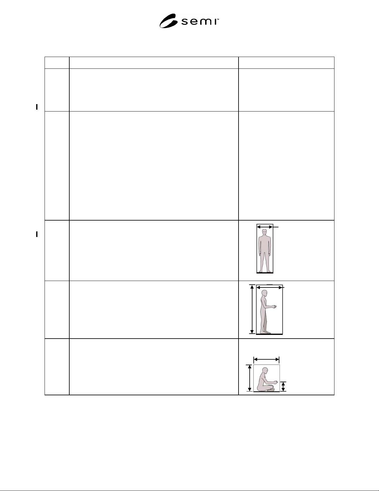
7.2.1 Any posture: upper body clearance (shoulder width)
A: Acceptance criterion: minimum 610 mm (24 in.)
A
7.2.2 Standing
B: Overhead clearance: minimum 1980 mm (78 in.)
C: Forward horizontal clearance: minimum 690 mm (27 in.)
C
B
7.2.3 Sitting-on-Floor
D: Overhead clearance: minimum 1000 mm (39 in.)
E: Forward horizontal clearance: minimum 690 mm (27 in.)
F: Working height: minimum 280 mm (11 in.)
E
D
F
SEMI S8-0705 © SEMI 1995, 2005 49
Section 7: Maintainability and Serviceability
Section Indicator Figure
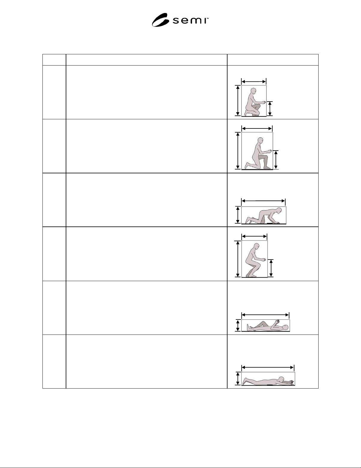
7.2.4 Squatting
G: Overhead clearance: minimum 1220 mm (48 in.)
H: Forward horizontal clearance: minimum 790 mm (31 in.)
I: Working height: minimum 460 mm (18.1 in.)
H
G
I
7.2.5
Kneeling
J. Overhead clearance (from floor): minimum 1450 mm (57 in.)
K. Forward horizontal clearance: minimum 1220 mm (48 in.)
L. Working height: minimum 640 mm (25.2 in.)
K
J
L
7.2.6 Kneeling Crawl:
M. Overhead clearance measured from floor: minimum 740 mm (29
in.)
N. Forward horizontal clearance: minimum 1520 mm (60 in.)
N
M
7.2.7
Stooping
O. Overhead clearance: minimum 1450 mm (57 in.)
P. Forward horizontal clearance: minimum 1020 mm (40 in.)
Q. Working height: minimum 640 mm (25.2 in.)
P
O
Q
7.2.8 Supine lying on back
R. Height (overhead): minimum 430 mm (17 in.)
S. Length (forward): minimum 1980 mm (78 in.)
S
R
7.2.9 Prone or crawl space
T. Height (overhead): minimum 510 mm (20 in.)
U. Length (forward): minimum 2440 mm (96 in.)
U
T