semi合集-English.pdf - 第7287页
SEMI MF847-0705 © SEMI 2003, 2005 7 15.2.3 Camera — having a fi lm holder with pr ovision f or establis hing precisely a horizont al refere nce line. This is convenientl y done by inst alling a li ght source with two lig…

SEMI MF847-0705 © SEMI 2003, 2005 6
11 Calculation
11.1 Calculate and record the average angular deviation as follows:
2
31
(1)
where:
= average angular deviation,
1
= first angle reading taken on goniometer, and
3
= second angle reading taken on goniometer.
12 Report
12.1 Report the following information:
12.1.1 Identity of samples tested including supplier and supplier lot identity,
12.1.2 Date of test and identity of operator making the measurements,
12.1.3 Specified flat and surface orientations, and
12.1.4 Measured values of
1
and
3
and the calculated value of
for each wafer.
13 Precision and Bias
13.1 The single-instrument, single-operator repeatability of this measurement was estimated by measuring one
wafer 50 times (25 times each side). This test yielded a distribution of calculated values of
with a 1-
value of
1.94 min.
TEST METHOD B — LAUE BACK REFLECTION X-RAY METHOD
14 Summary of Test Method
14.1 In this test method the wafer is mounted in a Laue back-reflection X-ray camera and a collimated beam of
“white” (continuous or Bremsstrahlung) radiation is directed at the wafer flat.
14.2 A spot is produced on the film for each set of crystal planes that satisfies the Bragg equation for any
wavelength component of the impinging radiation.
14.3 The pattern on the film is read with an engineering drafting head.
14.4 When the flat surface is within 5° of the specified low-index plane, the angle between the nearest zone of Laue
spots that goes through the center of the pattern and the zero reference line is a direct measure of the angular
deviation.
15 Apparatus
15.1 Commercially Available X-Ray Diffraction Apparatus — Utilizing a silver or tungsten tube as the X-ray source
and including a shutter to control the X-ray exposure.
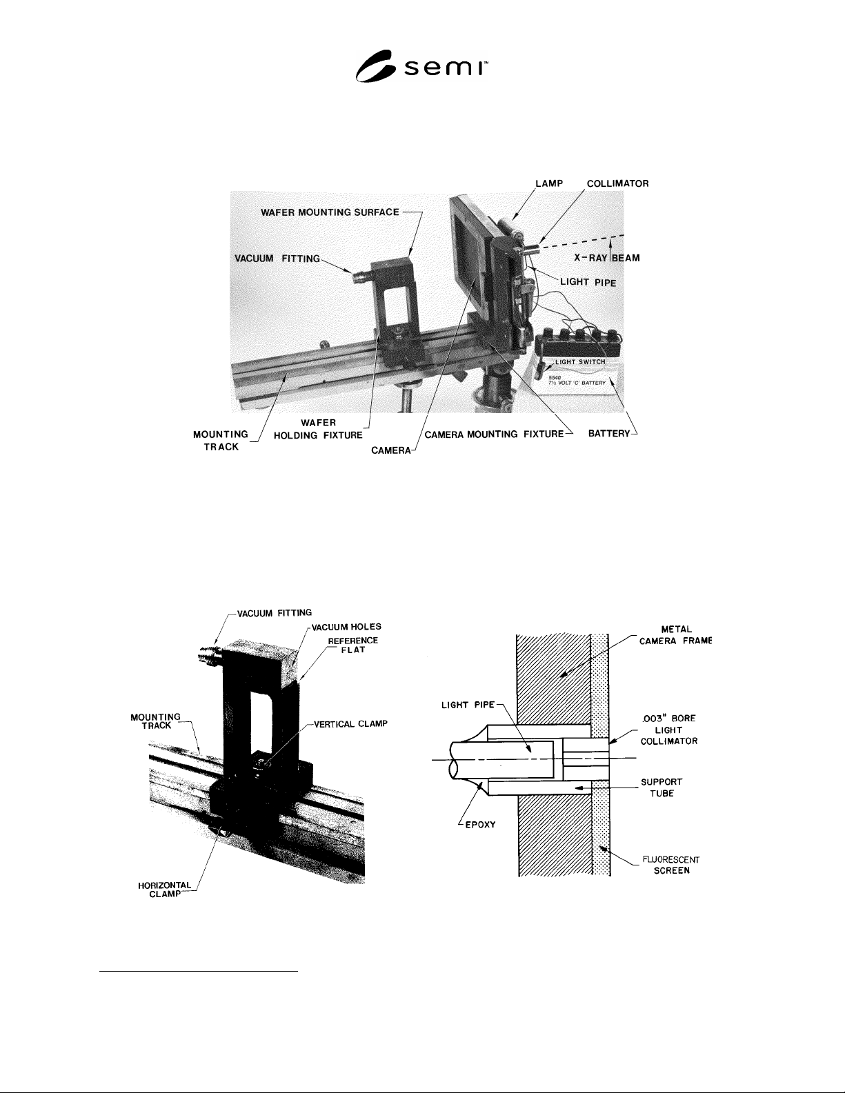
15.2 Laue Back-Reflection X-ray Camera — With the following features (see Figure 3):
15.2.1 Mounting Track — With the upper surface and one side round precision flat perpendicular to each other,
aligned with the X-ray beam from the source.
15.2.2 Wafer Holding Fixture — On which two plane surfaces are ground so that when it is clamped to the
mounting track one surface is perpendicular and the other is parallel with the horizontal (upper) surface of the
mounting track to 1 min of arc (29 m in 100 mm) (see Figure 4). The vertical surface contains holes connected to a
vacuum line through a fitting on the back of the fixture. In use, the flat is aligned to the horizontal reference surface
and the vacuum holds the wafer against the vertical surface.
SEMI MF847-0705 © SEMI 2003, 2005 7
15.2.3 Camera — having a film holder with provision for establishing precisely a horizontal reference line. This is
conveniently done by installing a light source with two light pipes and 75 m (0.003 in.) diameter light collimators
at the midpoint of the shorter dimension of the film, as near to the edges of the sensitive area of the film as possible
(see Figure 5). A tube for collimating the X-ray beam is required at the center of the film holder (see Figure 3).
NOTE: Use of high-speed “instant” film together with a fluorescent screen results in shorter test times than with wet-processed
films.
8
A holder of this type is commercially available. This holder has built into it four reference spots which define two
orthogonal lines which pass through the center of the film when the X-ray beam collimator is located (these reference spots are
not utilized in the present test method). If this type of holder is used, the collimator tube must not protrude above the surface of
the fluorescent screen because of film and clip interference problems during loading and processing of the film.
Figure 3
Photograph of Assembled View of Laue Camera and Wafer Holder
Figure 4
Photograph of Wafer Holding Fixture and
Mounting Track
Figure 5
Section of Laue Camera Platen Showing Light Pipe
and Collimating Tube
8 Schmidt, P. H., and Spencer, E. G., “X-Ray Diffraction Camera Using Polaroid Film,” Rev. Sci. Instrum. 35, 957–958 (1964).

SEMI MF847-0705 © SEMI 2003, 2005 8
15.2.4 Camera Mounting Fixture — For clamping the camera to the mounting track so that the collimator is aligned
with the X-ray beam and the horizontal reference line established by the light-generated dots is parallel with the
upper surface of the mounting track to 1 min of arc (29 m in 100 mm).
15.3 Drafting Head Protractor — With a clear plastic blade and finest vernier divisions of six min of arc or less for
reading the Laue photograph. A straight line, approximately 125 mm (or 5 in.) long, and in line with the centerpoint
of the protractor, is inscribed on the bottom of the plastic blade.
a. Schematic Representation
b. Actual Photograph
Figure 6
Laue Pattern
16 Procedure
16.1 Place the wafer to be tested on the wafer holding fixture so that the flat is resting securely against the reference
flat on the fixture. Turn on the vacuum to hold the wafer securely against the fixture.
16.2 Turn on the X-ray source, adjust the voltage and current (Note 4), and load the film into the camera. Open the
X-ray shutter and expose the film for an appropriate time (Note 5). During exposure, pulse the light to generate the
dots which define the horizontal reference line, and develop the film.
NOTE 4: For a tungsten X-ray tube typical voltage and current are 50 to 60 kV and 20 to 30 mA, respectively.
NOTE 5: Use of high-speed, instant film (ASA 300) and a fluorescent screen results in typical exposure times of 1 to 2 min.
16.3 Read the Laue pattern on the film.