semi合集-English.pdf - 第7376页
SEMI MF1392-1103 © SEMI 2003 20 RELATED INFORMATION 3 NUMERICAL CONSTANTS NOTICE: This related in formation is not an offi cial part of SEMI MF1392. It was develo ped during the original development of the document. This…
SEMI MF1392-1103 © SEMI 2003 19
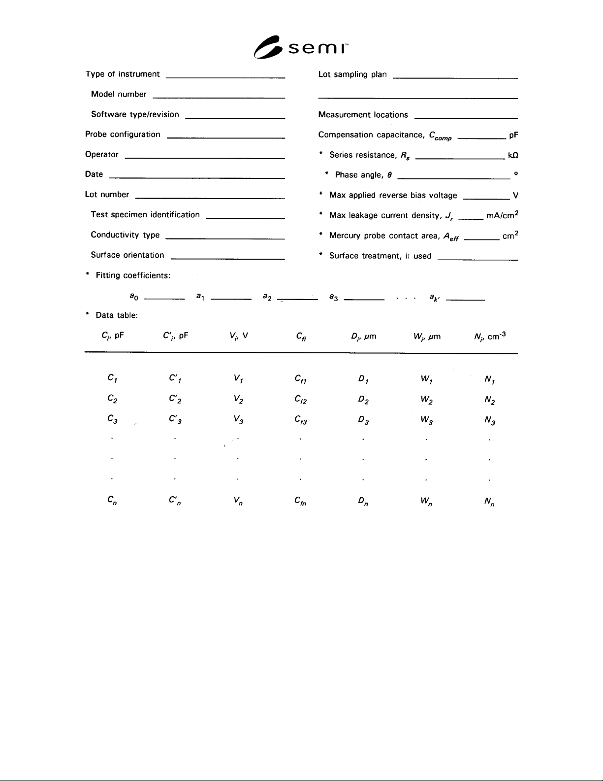
NOTE: Items marked with an asterisk (*) are required only for referee measurements.
Figure R2-2
Example of Format for Capacitance-Voltage Data and Calculations Using the Curve-Fitting Method
SEMI MF1392-1103 © SEMI 2003 20
RELATED INFORMATION 3
NUMERICAL CONSTANTS
NOTICE: This related information is not an official part of SEMI MF1392. It was developed during the original
development of the document. This related information was approved for publication by full letter ballot on July 12,
2003.
R3-1.1 The numerical constants given in the equations
in this test method are lumped constants. This appendix
provides details as to the composition of these lumped
constants and the values of the individual constants
used in deriving them. Table R3-1 gives the lumped
constants, their formulas, and their values. The units in
this table include any necessary unit conversions. If
there is no entry for a given equation, either there is no
lumped constant in the equation or the constant is
strictly numeric (for example, as for unit conversion).
Table R3-2 gives the values of the individual constants
used in this test method. The built-in potential, φ, may
vary from about 0.5 to about 0.8 V; the constant value
assumed is an approximation to this parameter.
Table R3-1 Lumped Constants
Equation Formula Value (Note 1)
(13), (17), (18)
φ
0.6 [V]
(14) (19a)
K
Si
ε
0
10359 [pF·µm/cm
2
]
(16)
K
Si
ε
0
/q 6.466 × 10
14
[(F·µm
−2
)/(C·cm
3
)]
(19b)
2/K
Si
ε
0
q 1.2050 × 10
−7
[(cm·F)/(C·pF
2
)]
NOTE 1: The units are given in brackets; the symbol C indicates
coulombs and the symbol F indicates farads.
Table R3-2 Values of Individual Constants
Constant Symbol Value (Note 1)
Built-in potential
φ
0.6 [V]
Permittivity of free space
ε
0
8.8542 × 10
−14
[F/cm]
Dielectric constant of silicon K
Si
11.7
Electronic charge q
1.6022 × 10
−19
[C]
NOTE 1: The units are given in brackets; the symbol C indicates
coulombs and the symbol F indicates farads.
NOTICE: SEMI makes no warranties or
representations as to the suitability of the standards set
forth herein for any particular application. The
determination of the suitability of the standard is solely
the responsibility of the user. Users are cautioned to
refer to manufacturer' s instructions, product labels,
product data sheets, and other relevant literature,
respecting any materials or equipment mentioned
herein. These standards are subject to change without
notice.
By publication of this standard, Semiconductor
Equipment and Materials International (SEMI) takes no
position respecting the validity of any patent rights or
copyrights asserted in connection with any items
mentioned in this standard. Users of this standard are
expressly advised that determination of any such patent
rights or copyrights, and the risk of infringement of
such rights are entirely their own responsibility.
Copyright by SEMI® (Semiconductor Equipment and Materials
International), 3081 Zanker Road, San Jose, CA 95134. Reproduction o
f
the contents in whole or in part is forbidden without express written
consent of SEMI.

SEMI MF1451-1104 © SEMI 2004 1
SEMI MF1451-1104
TEST METHOD FOR MEASURING SORI ON SILICON WAFERS BY
AUTOMATED NON-CONTACT SCANNING
This test method was technically approved by the Global Silicon Wafer Committee and is the direct
responsibility of the North American Silicon Wafer Committee. Current edition approved for publication by
the North American Regional Standards Committee on August 16, 2004. Initially available at
www.semi.org
September 2004; to be published November 2004. Original edition published by ASTM International as
ASTM F 1451-92. Last previous edition SEMI MF1451-0704.
1 Purpose
1.1 Sori can significantly affect the yield of
semiconductor device processing.
1.2 Knowledge of this characteristic can help the
producer and consumer determine if the dimensional
characteristics of a specimen wafer satisfy given
geometrical requirements.
1.3 Changes in wafer sori during processing can
adversely affect subsequent handling and processing
steps. These changes can also provide an important
process monitoring function.
1.4 This test method is suitable for measuring the sori
of wafers used in semiconductor device processing in
the as-sliced, lapped, etched, polished, epitaxial or other
layer condition and for monitoring thermal and
mechanical effects on the sori of wafers during device
processing.
2 Scope
2.1 This test method covers a non-contacting,
nondestructive procedure to determine the sori of clean,
dry semiconductor wafers.
2.2 This test method employs a two-probe system that
examines both external surfaces of the wafer
simultaneously.
2.3 The test method is applicable to wafers 50 mm or
larger in diameter, and approximately 100 m and
larger in thickness, independent of thickness variation
and surface finish, and of gravitationally induced wafer
distortion.
2.4 This test method is not intended to measure the
flatness of either exposed silicon surface. Sori is a
measure of the distortion of the front surface of the
wafer.
2.5 This test method measures sori of a wafer corrected
for mechanical forces applied during the test.
Therefore, the procedure described gives the
unconstrained value of sori.
NOTE 1: This sori is indicated by the acronym “GFLYFER”
in Appendix 2, Shape Decision Tree, of SEMI M1.
2.6 This test method includes several methods for
canceling gravity-induced deflection which could
otherwise alter the shape of the wafer.
1
NOTE 2: One of these methods, the Representative Wafer
Inversion Method, is covered by a patent held by ADE
Corporation, 80 Wilson Way, Westwood, MA 02090-1806.
NOTICE: This standard does not purport to address
safety issues, if any, associated with its use. It is the
responsibility of the user of this standard to establish
appropriate safety and health practices and determine
the applicability of regulatory or other limitations prior
to use.
3 Limitations
3.1 Any relative motion along the probe measuring axis
between the probes and the wafer holding device during
scanning will produce error in the measurement data.
Vibration of the test specimen relative to the probe-
measuring axis will introduce error. Such errors are
minimized by system signature analysis and correction
algorithms. Internal system monitoring may also be
used to correct non-repetitive and repetitive system
mechanical translations. Failure to provide such correc-
tions may cause errors.
3.2 If a measured wafer differs substantially in
diameter, thickness, fiducials, or crystal orientation
from that used for the gravitational compensation
procedure, the results may be incorrect. Estimates of
the errors in gravity induced deflection for differences
in diameter and thickness are shown in Related
Information 1. If the crystal orientation of the sample
to be measured differs from the crystal orientation of
the gravity-compensation wafer, then the measured sori
value may differ from the actual sori value by up to
15%. Error tables for fiducial variation have not been
generated.
3.3 Different methods for implementing gravitational
compensation may give different results. Varying
1 Poduje, N., “Eliminating Gravitational Effect in Wafer Shape
Measurements,” NIST/ASTM/SEMI/SEMATECH Technology Confe-
rence, Dallas, TX. Technology for Advanced Materials/Process
Characterization, February 1, 1990.