semi合集-English.pdf - 第1644页
SEMI E38-1296 © SEMI 1995 , 1996 33 TM = Transport Modu le PM1 = Process ing Module #1 PM2 = Process ing Module #2 The general ro uting for the sce nario is illustrated in the message sequ e nce below : 1. A cas sette of…
SEMI E38-1296 © SEMI 1995, 1996 32
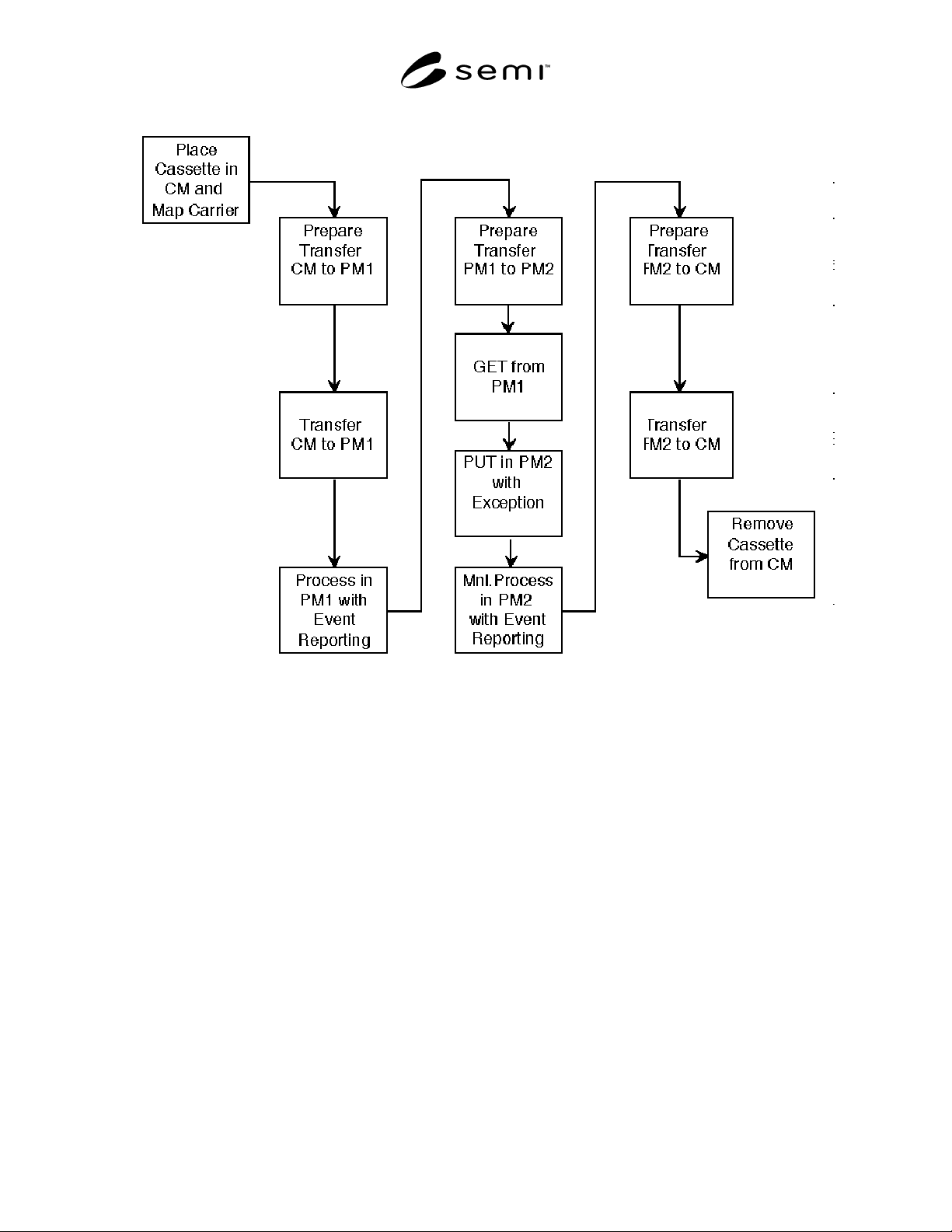
Figure 20
Typical Operating Scenario
A1-2 Typical Operating Scenario
The purpose of this section is to give an example of a
typical operating scenario that will illustrate the various
services being used to perform cluster tool control
functionality. This operating scenario is NOT intended
to be the only scenario to be implemented in a
standards-compliant cluster. The intent is to provide
guidance in navigating the various services standards.
An exhaustive use of Object Services and Exception
Management Services will not be done since these two
areas tend to be very application-specific.
This scenario concentrates on the material processing,
material movement aspects of the cluster-specific
services.
The operating scenario shown in Figure 20 will be
given in the form of a communication timing diagram
with messages being sent between the various cluster
tool components and will be indicated in the following
manner:
ServiceGroup_ServiceName.Request or Response
(Service Parameters)
Example: TRJobCreate.Req(...)
• TR is the service group that contains the service,
the material movement services.
• JobCreate is the service being used to cause
communication to take place between two cluster
tool components. Specifically, this service is the
material movement service that initiates the
transfer of material between modules.
• Req indicates that the service is a Request.
• (...) indicates any other parameters that might be
present with the service definition and will be
service-dependent.
Definitions:
CC = Cluster Controller
CM = Cassette Module

SEMI E38-1296 © SEMI 1995, 199633
TM = Transport Module
PM1 = Processing Module #1
PM2 = Processing Module #2
The general routing for the scenario is illustrated in the
message sequence below:
1. A cassette of wafers arrives from the factory and is
given to the cassette module.
2. A mapping of the wafers in the various slots of the
cassette is determined for use inside the cluster.
3. A transfer job is initiated to move a wafer from the
cassette to a process module (in this case PM1).
4. The cassette module is commanded to send the
wafer to the transport module.
5. The PM1 is instructed to create the process job and
to retrieve any pertinent recipe information in order
to process the wafer.
6. The wafer is handed off between the cassette
module and the transport module (Wafer GET
operation).
7. The wafer is handed off between the transport
module and PM1 (this is a Wafer PUT operation).
8. The wafer is processed in PM1.
9. A transfer job is initiated to the transport module to
move a wafer from PM1 to PM2.
10. The PM1 is commanded to send the wafer to the
transport module.
11. The PM2 is instructed to create the process job and
to retrieve any pertinent recipe information in order
to process the wafer.
12. The wafer is handed off between the PM1 and the
transport module with a GET.
13. The wafer is handed off between the transport and
PM2 with a PUT.
14. The wafer is processed in PM2 when manually
started.
15. A transfer job is initiated to the transport module to
move a wafer from PM2 back to the cassette
module.
16. The PM2 is commanded to send the wafer to the
transport module.
17. The cassette module is instructed to receive the
wafer.
18. The wafer is handed off between PM2 and the
transport module.
19. The wafer is handed off between the transport
module and the cassette module.
20. The cassette module is instructed to send the
cassette to the factory.
1. FACTORY TO CM CASSETTE HANDOFF
The cassette containing a single wafer in wafer slot 1 to
be processed by the cluster tool is passed from the
factory environment to the cluster tool.
At this point the user (human or host) will be prompted
to place the cassette on the cassette module loading
system. The cassette module is then informed to receive
a cassette from the external environment.
CC CM
>>------------------------------------->>
TRJobCreate.Req(MID="Carrier1",Port=Port2
, Dir=Receive)
CC CM
<<-------------------------------------<<
TRJobCreate.Rsp(JobID=IOJob1,Status=OK)
The cassette module prepares to receive the cassette by
such actions as loadlock venting, door opening, and
then requesting handoff from the Factory.
CC CM
<<-------------------------------------<<
TRJobStarted.Req(JobID=IOJob1, TimeStamp)
The actual cassette transfer takes place, the cassette
module takes such actions as door closing and loadlock
pumping down to internal transfer pressures, and then
reports completion of the material transfer.
CC CM
<<-------------------------------------<<
TRJobComplete.Req(JobID=IOJob1,TimeStamp,
Status=OK))

SEMI E38-1296 © SEMI 1995, 1996 34
2. WAFER MAPPING
The wafers in each of the cassette wafer slots are
assigned a unique wafer ID. In this case, the wafer is
identified as “Wafer1.” If there were more than one
wafer, this process would be repeated until all the
wafers had been given their appropriate identification
that is used later when specific wafers are requested for
transfer and processing.
CC CM
>>------------------------------------->>
Set.Req("WAFERSLOT",SlotID=1,MID=
"Wafer1")
CC CM
<<------------------------------------<<
Set.Rsp("WAFERSLOT",SlotID=1,Status=OK)
3. CC TO TM TRANSFER JOB SETUP
The CC informs the TM that a wafer transfer is required
from the CM to PM1.
CC TM
>>------------------------------------>>
TRJobCreate.Req(MID="Wafer1",TRSourceAmID
="CM",TRDestinationAmID="PM1")
The transport module assigns an identifier for this
particular transfer job. This is important in an actual
cluster implementation since multiple transfer jobs may
be queued and active at any given time. The transfer job
is then started by the transport module.
CC TM
<------------------------------------<<
TRJobCreate.Rsp(JobID=TMJob1,Status=OK)
CC TM
<<-------------------------------------<<
TRJobStarted.Req(JobID=TMJob1,TimeStamp)
4. CC TO CM SEND WAFER
The CC informs the CM that a wafer is to be transferred
to the TM.
CC CM
>>------------------------------------->>
TRJobCreate.Req(MID="Wafer1",PortID=
"Port1",Dir=Send)
CC CM
<<-------------------------------------<<
TRJobCreate.Rsp(JobID=IOJob2,Status=OK)
When the cassette module is ready, it directly
communicates with the cluster controller and the
transport module to indicate its readiness for wafer
handoff.
CC CM
<<-------------------------------------<<
TRJobStarted.Req(JobID=IOJob2, TimeStamp)
TM CM
<<-------------------------------------<<
HOReady.Req(PortID="Port1",AmID="CM",
HODir=GET,MID="Wafer1")
5. CC TO PM1 PROCESSING JOB SETUP
The CC informs PM1 that a wafer will be delivered
(which requires a TRJob to be created) and is to be
processed (this requires that a process job be
established). This involves creating the jobs and
transferring the appropriate recipes to the process
module as required. At some point in this process, the
PM will inform the transport module that it is ready to
receive the wafer with the issuing of the HOReady
Request.
The CC informs PM1 that a wafer is to be transfered
from the TM.
CC PM1
>>------------------------------------>>
TRJobCreate.Req(MID="Wafer1",Port="Port1"
, Dir=Receive)
CC PM1
<<------------------------------------<<
TRJobCreate.Rsp(JobID=IOJob3,Status=OK)
When the process module is ready, it directly
communicates with the cluster controller to indicate its
readiness for wafer handoff.
CC PM1
<<-------------------------------------<<
TRJobStarted.Req(JobID=IOJob3, TimeStamp)
The process job is created on the process module.
CC PM1
>>------------------------------------->>
PRJobCreate.Req(RecID="PP1",MID="Wafer1")
CC PM1
<<-------------------------------------<<
PRJobCreate.Rsp(JobID=PM1Job1,Status=OK)
CC PM1
<<-------------------------------------<<
PRJobSetup.Req(JobID=PM1Job1)