semi合集-English.pdf - 第3675页
SEMI PR8-0703 © SEMI 2003 5 Covered in Section # Feature Description Supported By Interface Definition Implementation Required Data Collection Plans 7.9 The data to be transmitted through the EDA port shall be defined in…
SEMI PR8-0703 © SEMI 2003 4
Table 1 EDA Interface Features
Covered in
Section #
Feature Description
Supported By
Interface Definition
Implementation
Required
General Interface
7.1.3 Messages are communicated via Ethernet using HTTP on top o
f
TCP/IP as the message transport.
! !
7.1.9 Messages are represented as XML data within SOAP
envelopes.
! !
7.7.3.2 Data collection events, state model transitions, equipment
exceptions, and parametric data defined by existing software
standards (such as SEMI E30, E40, E87, E90, E94, etc…) that
are made available through the SECS/GEM interface are
supported.
!
Optional
7.7.3.2 Transmission of milestones or tasks during subsystem
processes, actuator operations, is supported.
!
Optional
7.7.2 A time resolution of 0.01 seconds is supported in messages
requiring a timestamp.
!
Optional
Data Collection Management
7.6.2.7 Ability to list the names of, and activate/de-activate data
collection plans via the EDA interface is supported.
! !
7.6.2.6 Ability to list the names of, and activate/de-activate data
collection plans via the –SECS/GEM interface is supported.
! !
7.4.1 Equipment configuration is provided to switch listing/activation
of data collection plans to either the SECS/GEM or the EDA
interface.
-
!
7.4.4 Multiple data collection clients are supported.
!
Optional
7.7.4 Ability to warn clients of equipment performance degradation
is supported.
! !
7.9 The equipment shall provide a method for the user to modify,
add and delete data collection plans.
-
!
7.9 The equipment shall provide a method for the user to view the
contents of the data collection plans.
-
!
7.6.2.2 The equipment shall provide the names of Data Collection
Plans available for selection/activation by applications through
the interface.
! !
7.6.2.6.1 Data transmission will continue independent of the SECS/GEM
communication state of the equipment.
-
!
Security
7.4.2, 7.6.2 Ability to specify the URI of data consumers and data managers
at the equipment is supported.
-
!
Metadata
7.8 Equipment metadata is accessible to off-tool clients. -
!
7.8 Metadata shall include the equipment’s physical structure down
to the level of each individual sensor/actuator that can be
included in a data collection plan.
-
!
7.8 Metadata shall include the names and definitions of any
parameters that can be included in a data collection plan.
-
!
7.8 Metadata shall include the possible exceptions or errors that can
be included in data collection plans.
-
!
7.8 Metadata shall include what transitions from SEMI standard
and equipment supplier defined state models are available
through the EDA port.
-
!
SEMI PR8-0703 © SEMI 2003 5
Covered in
Section #
Feature Description
Supported By
Interface Definition
Implementation
Required
Data Collection Plans
7.9 The data to be transmitted through the EDA port shall be
defined in a set of named data collection plans.
-
!
7.9 Data collection plans shall describe which events, exceptions,
data variables will be sent through the interface when that plan
is activated.
-
!
6.3 Risks for Preliminary Implementations
6.4 There are some inherent risks to implementers of
the EDA interface specified in this document.
Significant risks include:
6.4.1 TCP/HTTP Limitations on Data Latency — Any
use of this standard in an application requiring
deterministic latency in the communication of data to
an off-tool application is at risk of failure due to late
delivery of data. Occasional delays in data delivery on
the order of a second or more can occur in TCP
communication due to the need for packet
retransmission. This is inherent in the TCP/IP protocol
used by HTTP, and cannot be addressed through
application design.
6.4.2 Data Collection Plan and Metadata Structure
and Formats are not Specified — The content and
transmission format of Data Collection plans and
Metadata for the proposed standard are left up to the
supplier. Standards are in process to define Metadata
and data collection plan content and data transmission
format in a standard way. The standard definitions may
be different than those defined by the supplier for the
proposed standard.
6.4.3 SOAP Protocol Usage — The SOAP usage
defined in this standard is targeted for point-to-point,
synchronous communication. This style of SOAP
communication may not be suitable for more
complicated communication models, and other
approaches may be required to achieve the objectives of
such applications.
6.4.4 XML/SOAP Limitations on Data Throughput —
While much has been done to optimize commercial
implementations of XML/SOAP messaging support,
end-to-end implementations on semiconductor
equipment have not been studied to quantify the
performance limitations of these technologies for data
collection, or to identify what hardware/software
configuration options are significant factors in
providing optimal throughput performance with these
technologies. If an implementation of this standard
requires meeting specific data throughput goals, it may
be necessary to evaluate the choice of networking
software drivers, application design, messaging
software toolkits used, hardware memory/cpu resources
or other elements when designing an implementation of
this specification. If the desired throughput goals
cannot be met by these design options, it may impact
the design of the message specification, the choice of
transport, or the mechanism for encoding the data
described in this specification.
NOTE 1: For information on factors contributing to SOAP
messaging performance, see http://www.extreme.indiana.edu/
~ mgovinda/research/papers/soap-hpdc2002.pdf
NOTE 2: For information on factors contributing to HTTP
performance, see http://www.w3.org/Protocols/HTTP/
Performance/
NOTE 3: For information purposes only, one example of
possible worst-case data throughput expectations for FDC
applications is available at http://www.sematech.org/public/
resources/ediag/background/eec032702.pdf.
7 Proposed EDA Interface Specification
7.1 Transport and Messaging
7.1.1 XML Schema Namespace — All XML element
information items defined in this specification belong to
the reserved SEMI namespace “urn:semi-
org:schema:eda_ps_v0.0”.
7.1.2 Separate Data Port — The proposed Equipment
Data Acquisition interface shall be a separate logical
port from the SECS/GEM control port on the tool.
7.1.3 Transport Mechanism — The transport
mechanism for the proposed EDA interface shall be
HTTP 1.1. The HTTP POST operation shall be used to
send messages to and from the equipment. There shall
be an HTTP connection from the equipment to the
client used for data only and another HTTP connection
from the client to the equipment, which will be used for
data management. These two HTTP connections
together make up a single EDA interface.
7.1.4 HTTP Performance Features — The client of the
equipment’s data port must operate in persistent
connection mode, as defined in HTTP 1.1. It is not
required that the data management connection of the
EDA port operate in persistent connection mode,
though that is the default mode for HTTP 1.1.
SEMI PR8-0703 © SEMI 2003 6
7.1.5 SOAP Binding — The SOAP binding specified in
this document shall be HTTP 1.1 in accordance with the
SOAP 1.1 W3C Note.
7.1.6 SOAP Message Style — Message encoding will
be XML document-style and not Remote Procedure
Call style. In document-style message exchange, XML
documents conforming to some application-defined
schema are exchanged via SOAP messages.
7.1.7 SOAP Action — The SOAP action HTTP header
field is used to facilitate dispatching individual
messages defined by this specification. The field will
contain a URI that indicates the specific operation in
the message. The URI will be a URN of the form:
“urn:semi-org:ws:eda_ps_v0.0:<OperationName>”.
Where OperationName corresponds to the name of the
root tag for each message.
7.1.8 SOAP Headers — This document specifies the
required use of a SOAP header element to describe the
source and destination of all messages between the
equipment and EDA clients (see Section 7.3.2 and to
correlate responses with requests (see Section 7.3.3).
The specification does not prohibit the use of additional
SOAP header elements, should an implementation of
this specification find them necessary.
7.1.9 SOAP encodingStyle — The SOAP
encodingStyle attribute is not used (i.e., not present on
any XML element information item) for the messages
defined in this specification.
7.1.10 SOAP Body — The SOAP body will contain an
XML fragment as defined in the Data Management and
XML Data Formats sections below.
7.2 SOAP Message Structure
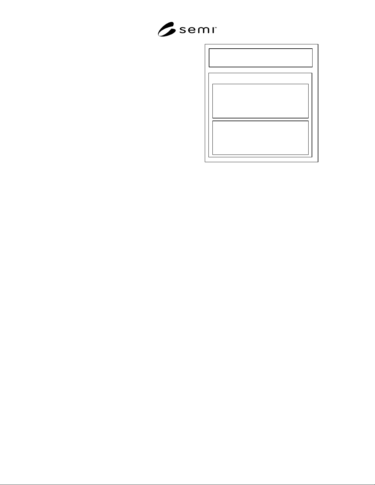
7.2.1 Figure 3 shows the organization of each SOAP
message exchanged between the equipment and EDA
clients. This specification defines the value of the
SOAPAction HTTP header to use for each message
(see Sections 7.6.2.1 through 7.6.2.5), the SOAP
headers to be used for each message (Section 7.3), and
the elements that are included in the body of the SOAP
envelope for each message (see Sections 7.6.2.7 and
7.7).
HTTP Headers
SOAPAction
SOAP Envelope
SOAP Headers
<MessageHeader>
<From />
<To />
<CorrelationId /> (optional)
</MessageHeader>
SOAP Body
<IsEdaEnabled />, or
<ActivatePlan />, or
<EdaData />, or
<GetDefinedPlanIdsResponse />,
Etc.
Figure 3
EDA Message Structure
7.3 SOAP Headers
7.3.1 This section describes a SOAP header element
(MessageHeader) that can be used to facilitate different
messaging implementations on both the equipment and
EDA client side of the interactions defined in this
specification. The SOAP header defined in this section
is provided to identify the sender and recipient of each
SOAP message included in this specification, and to
associate a specific message with other messages sent
by a given entity.
7.3.2 There are two elements specified for the purpose
of identifying the sender and intended recipient of a
SOAP message: a “From” element and a “To” element.
Both are required elements in the MessageHeader
element of each message exchanged in an
implementation of this specification. These elements
identify the sender or intended recipient of a given
SOAP message. These identifiers can be used to route
a message to an appropriate entity for processing, to
distinguish a specific message from other messages
received from other sources, or as a simple mechanism
for enforcing access controls.
7.3.3 This section also defines an optional element
(“CorrelationId”) within the MessageHeader element
that can be used to associate related messages (for
example, a request and its reply) among all messages
sent and received by a given entity. The entity in the
client role generates a value for the CorrelationId that
would be used by the server entity in its reply to
establish the correlation. Use of this element is
optional, and communicating entities are not required to
process it in order to exchange the messages in this
specification.