semi合集-English.pdf - 第6065页
SEMI G10-96 © SEMI 198 6, 1996 2 7 Procedure for Strip Pitch ( X -Axis ) (See Figure 2) Equipment — Optical comparator (20× lens), piece part drawi ng. 7.1 All measurements will be ta ke n fro m the pilot holes referred …

SEMI G10-96 © SEMI 1986, 19961
SEMI G10-96
STANDARD METHOD FOR MECHANICAL MEASUREMENT OF
PLASTIC PACKAGE LEADFRAMES
1 Purpose
This method outlines standard mechanical measurement
techniques for cut strip leadframes.
2 Scope
This method applies to all facilities that perform
mechanical measurements on leadframes. Information
is provided herein to enable the use of the following
specifications: SEMI G9, SEMI G27, and SEMI G28.
3 Referenced Documents
None.
4 Terminology
None.
5 Equipment
1. Surface illuminated optical comparator with x-y
grid
2. Toolmaker’s microscope with depth (“z”) reading
capability, 100×, 400×, obtained with 10× objective,
and 40× objective lens with 0.0002" resolution.
a. Digital readout 0.0002" resolution on x-axis
(optional)
b. Closed circuit TV and camera (optional)
3. Surface plate
4. Gage pins
5. Universal leadframe fixture (see Figure 16)
a. Fixture shall be perpendicular to optics within
the resolution of the instrument and parallel to x
and y travel axes.
b. Leadframe strip shall be placed lead-flat surface
up and clamped at rails to fixture base.
c. The reference plane for measurement,
hereinafter called the “z” plane, is the average of
the height of the two dambars when measured at
their geometric center.
d. Z-plane cannot be established by this method if
the dambar height measurement difference is
greater than 0.003". Therefore, units that exhibit
greater than 0.003" difference are not acceptable
for z-axis measurement.
6. Leadframe camber fixture
a. Nominal strip orientation defined in Figure 8.
7. Lead fatigue tester
8. Metal-to-metal clearance step gage (see Figure 13)
9. 0-1", 0.0001" reading micrometer
10.Overlay (see Figure 17)
a. Overlay reference point shall be based on strip
pilot holes. If pilot holes are off screen, x-y
offsets of overlay pilot position to actual pilot
position shall be specified.
b. True position targets shall be placed on nominal
lead center line 0.0065" (0.163 mm) back from
nominal lead tip.
c. Overlay will contain nominal pad location
outline.
d. Overlay will contain nominal strip cutoff
position and required x-axis traverse for
alignment.
6 Procedure for Lead Twist (Z-Axis) (See
Figure 1)
Equipment — Toolmaker’s microscope (400×
magnification), leadframe fixture.
6.1 Fixture leadframe and establish z-plane as
described in Section 5, items 5a and 5b.
6.2 Focus microscope on the edge of the coined
surface 0.010" back from the end of the lead tip on the
lead to be measured. Ensure that the focus is done on
the flat-coined surface and not on the rolled edge. Zero
the focal height (z-axis).
6.3 Using the micrometer drum, move the stage the
specified distance and refocus the microscope. Ensure
that both focus points are on the flat-coined surface, and
not on the rolled edge. Focal height difference is the
lead twist measurement.
SEMI G10-96 © SEMI 1986, 1996 2
7 Procedure for Strip Pitch (X-Axis) (See
Figure 2)
Equipment — Optical comparator (20× lens), piece part
drawing.
7.1 All measurements will be taken from the pilot
holes referred to on the piece part print unless otherwise
noted.
7.2 Line up the pilot holes at each end of the strip so
that they are in the same horizontal plane. Center the
pilot hole by rotating the comparator screen 45° (Figure
3). Ensure that the vertical and horizontal lines (now at
45°) are tangent to the edge of the pilot hole. Zero the
readout, move the stage (horizontal travel) to the proper
pilot hole at the end of the strip. Center the specified
pilot hole on the strip. Read the horizontal readout for
the strip pitch measurement.
8 Procedure for Pad Tilt (Z-Axis)
(See Figure 4)
Equipment — Toolmaker’s microscope (100×
magnification), leadframe fixture.
8.1 Fixture leadframe and establish z-plane as
described in Section 5, items 5a and 5b.
8.2 All targets are to be located .005" (.127 mm) in
from cut edge, ensuring that the target is not located on
the rolled edge.
8.3 Focus the toolmaker’s microscope on one target
crossbow (A), zero focal height (z-axis).
8.4 Use the barrel micrometer to move to the second
target (B) of the die-attach pad. Note traverse distance
for extrapolation of specification. Refocus the
microscope. The focal height (z-axis) difference is the
tentative pad tilt measurement.
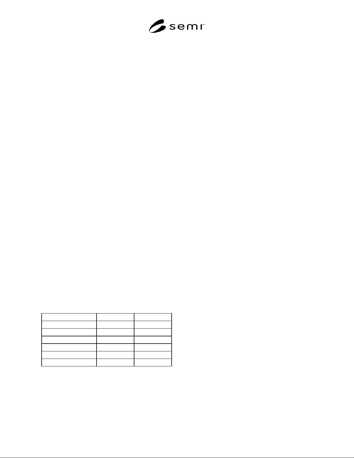
8.5 Repeat at targets shown in Table 1.
Table 1 Measurement Targets
AB
2 Tie bars 1 2
34
3 or more 1 2
Tie bars 3 4
13
24
8.6 Pad tilt is worst case of tentative measurements
taken per Table 1.
9 Procedure for Camber (See Figure 5)
Equipment — Camber fixture
9.1 Place the part to be measured in the camber fixture
on the comparator table. Ensure the strip rests against
the gage pins.
9.2 Place the horizontal center line on the strip edge
then down at the aperture.
9.3 This dimension, less gage distance, is the camber
measurement. Traverse the stage to bring the horizontal
center line to the reference edge.
10 Procedure for Crossbow ( See Figure 6)
Equipment — Toolmaker’s microscope (100×
magnification), leadframe fixture.
10.1 Fixture leadframe and establish z-plane as
described in Section 5, items 5a and 5b.
10.2 Focus the toolmaker’s microscope on the center
of top rail above the dambar (1). Zero focal height (z-
axis).
10.3 Move to the center of the opposite rail above the
dambar (2) and refocus. Average these two focal
heights to establish the base zero focal height.
10.4 Move to the center of the dambar (3) and refocus.
Focal height difference to base zero focal height is the
crossbow measurement.
11 Procedure for Lead Plana rity
(See Figure 7)
Equipment — Toolmaker’s microscope (100×
magnification), leadframe fixture.
11.1 Fixture leadframe and establish z-plane as
described in Section 5, items 5a and 5b.
11.2 Focus the toolmaker’s microscope on the center
of the dambar (1), then zero the focal height (z-axis).
11.3 Move to the center of the opposite dambar (2)
and refocus. Average these two focal heights to
establish the base zero focal height.
11.4 Move to subject lead (3) and refocus .010" (.254
mm) back from the lead tip. Note z-axis difference to
base zero focal height. Subtract measured coin depth to
give actual planarity measurement. Repeat above
procedure for all leads to be measured. Be sure to
record the plus (+) or minus (–) sign for each reading.
12 Procedure for Downset (S ee Figure 9)
12.1 Fixture leadframe and establish z-plane as
described in Section 5, items 5a and 5b.
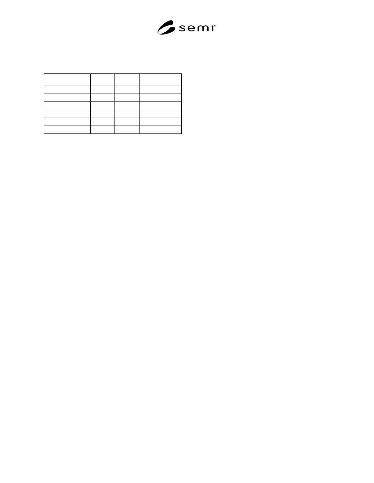
12.2 Focus the toolmaker’s microscope at the location
numbered in Column A of Table 2 and zero the focal
height (z-axis). Move the workholder so that the
corresponding location from Column B is under the
SEMI G10-96 © SEMI 1986, 19963
microscope and refocus. The difference in readings is
the downset measurement.
Table 2
A B Destination
P-dip 1 2 Bottom
34 Top
Quad 1 2 1st Quad
3 4 2nd Quad
5 6 3rd Quad
784th Quad
12.3 Repeat this for all tie bars indicated in Table 2.
12.4 All measurements must fall within the
specification that applies.
13 Procedure for Coil Set (See Figure 10)
Equipment — Surface plate, gage pins
13.1 Place the strip on the surface plate, bond target
side down, depressed pad up.
13.2 Slip gage pins under until you find the largest
size that will fit under freely at possible locations
shown. Pin diameter is the coil set measurement, noting
the + or designation of coil set direction per Figure l0.
14 Procedure for Pad Planari ty (Z-Axis) (See
Figure 11)
Equipment — Toolmaker’s microscope (100×
magnification), leadframe fixture.
14.1 Fixture leadframe and establish z-plane as
described in Section 5.5.
14.2 Move to the center of the die-attach pad (3) and
refocus. The focal height difference is the pad planarity
measurement.
15 Procedure for Burrs (X, Y, Z-Axis)
15.1 Vertical Burrs — (See Figure 12.)
Equipment — Toolmaker’s microscope (400×
magnification), leadframe fixture.
15.1.1 Fixture leadframe lead flat down and establish
z-plane as described in Section 5, items 5a and 5b.
15.1.2 Focus the toolmaker’s microscope on point A.
Zero the focal height (z-axis).
15.1.3 Move to the top of the burr (Point B) and
refocus the toolmaker’s microscope. The focal height
difference is the height of the vertical burr.
15.2 Horizontal Burrs (X, Y-Axis) — (See B, Figure
12.)
Equipment — Toolmaker’s microscope (400×
magnification).
15.2.1 Measure the horizontal burrs using the
toolmaker’s microscope in a similar manner to that
described in 15.1.2 and 15.1.3.
15.2.2 Line up the cut edge (Point C) with the 0 center
line on the toolmaker’s microscope. Record the number
on micrometer drum.
15.2.3 Move the stage to align the centerline with the
end of the burr (Point D). The lateral movement
(difference between start/end micrometer reading) will
be the burr dimension.
16 Procedure for Pits, Slug M arks, Tool Marks
(X, Y, Z-Axis), and Horizontal Burrs (See Figure
14)
16.1 Depth (Z-Axis)
Equipment — Toolmaker’s microscope (400×
magnification), leadframe fixture.
16.1.1 Fixture leadframe and establish z-plane as
described in Section 5, items 5a and 5b.
16.1.2 Focus the toolmaker’s microscope on the base
of the material near the defect, then zero the focal
height (z-axis).
16.1.3 Move to the pit, slug mark, or tool mark.
Refocus on the deepest portion. The focal height
difference (z-axis) is the depth of the pit, tool mark, or
slug mark.
16.2 Surface Dimension, Length, Width (X,Y-Axis)
Equipment — Toolmaker’s microscope (400×
magnification), leadframe fixture.
16.2.1 Fixture leadframe and establish z-plane as
described in Section 5, items 5a and 5b.
16.2.2 Line up to edge of the pit, slug mark, or tool
mark on the cross hair. Note the micrometer drum
reading.
16.2.3 Move to the opposite side of the pit, slug mark,
or tool mark. The lateral movement (difference between
start/end micrometer readings) is the pit, slug mark, or
tool mark surface dimension.
17 Procedure for X-Y Dimensional
Measurement
Equipment — Surface lit optical comparator, true
position overlay, metal-to-metal step gage.