semi合集-English.pdf - 第4286页
SEMI F81-1103 © SEMI 2003 1 SEMI F81-1103 SPECIFICATION FOR VI SUAL INSPECTION AND ACCEPTANCE OF GAS TUNGSTEN ARC (GTA) WELD S IN FLUID DISTRIBUTION SYSTEMS IN SEMICONDUCTOR MA NUFACTURING APPLICATIONS This specification…
SEMI F80-1103 © SEMI 2003 5
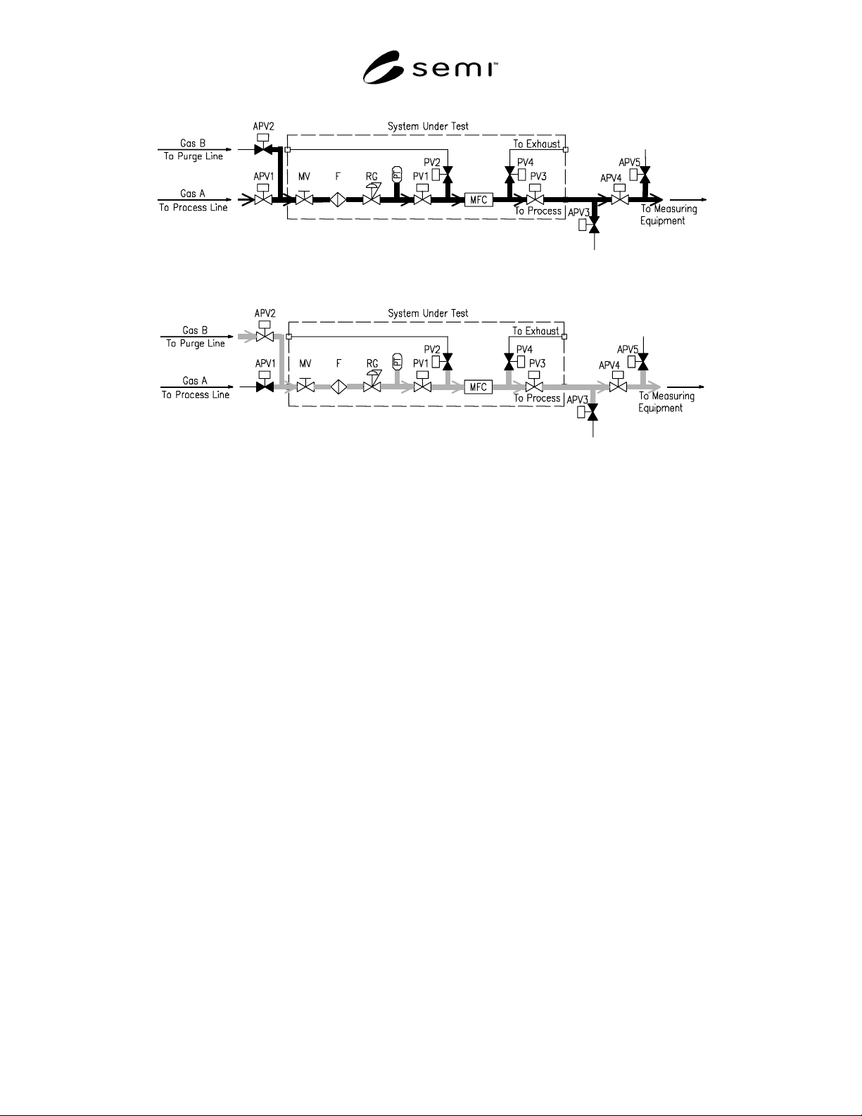
Figure 11
Procedure 7.2.6
Figure 12
Procedure 7.2.7
8 Reporting Results
8.1 The following items shall be stated on the test
report.
• Test date and time,
• Name of an operator,
• Test temperature,
• Flow rate of Gas A and Gas B,
• Name of Gas A and Gas B,
• Pressure of Gas A and Gas B,
• Name of the measuring equipment and model,
• Measuring condition of the measuring equipment
(ex. APIMS: Scan time, Mass range, and
measuring range),
• Minimum detectable limit of the measuring
equipment, and
• Relationship between gas concentration and test
time.
NOTICE: SEMI makes no warranties or
representations as to the suitability of the standards set
forth herein for any particular application. The
determination of the suitability of the standard is solely
the responsibility of the user. Users are cautioned to
refer to manufacturer' s instructions, product labels,
product data sheets, and other relevant literature,
respecting any materials or equipment mentioned
herein. These standards are subject to change without
notice.
By publication of this standard, Semiconductor
Equipment and Materials International (SEMI) takes no
position respecting the validity of any patent rights or
copyrights asserted in connection with any items
mentioned in this standard. Users of this standard are
expressly advised that determination of any such patent
rights or copyrights, and the risk of infringement of
such rights are entirely their own responsibility.
Copyright by SEMI® (Semiconductor Equipment and Materials
International), 3081 Zanker Road, San Jose, CA 95134. Reproduction o
f
the contents in whole or in part is forbidden without express written
consent of SEMI.
SEMI F81-1103 © SEMI 2003 1
SEMI F81-1103
SPECIFICATION FOR VISUAL INSPECTION AND ACCEPTANCE OF
GAS TUNGSTEN ARC (GTA) WELDS IN FLUID DISTRIBUTION
SYSTEMS IN SEMICONDUCTOR MANUFACTURING APPLICATIONS
This specification was technically approved by the Global Gases Committee and is the direct responsibility of
the North American Gases Committee. Current edition approved by the North American Regional Standards
Committee on September 3, 2003. Initially available at www.semi.org October 2003; to be published
November 2003.
1 Purpose
1.1 The purpose of this specification is to provide
visual inspection and acceptance criteria for gas
tungsten arc (GTA) welds of stainless steel and other
corrosion resistant metals and alloys (CRAs) in fluid
(liquid or gas) distribution systems in semiconductor
manufacturing applications. These criteria are meant to
ensure that welds are of sufficient quality to provide the
required system purity, weld integrity, and weld
strength for use in semiconductor manufacturing
applications.
2 Scope
2.1 This specification defines inspection and
acceptance criteria for GTA autogenous butt joint welds
of stainless steel and other CRAs in fluid distribution
systems. The fluid distribution system includes tubing,
pipe, fittings, valves, subassemblies and components
that contain and distribute fluid.
NOTICE: This standard does not purport to address
safety issues, if any, associated with its use. It is the
responsibility of the users of this standard to establish
appropriate safety and health practices and determine
the applicability of regulatory or other limitations prior
to use.
3 Limitations
3.1 The stainless steels covered by this specification
are limited to the austenitic and superaustenitic grades
of stainless steel.
3.2 Corrosion resistant metals and alloys covered by
this specification are limited to solid solution grades of
nickel alloys and solid solution grades of titanium
alloys.
3.3 This specification applies only to autogenous GTA
circumferential butt joint welds performed on fluid
distribution system components 6 inches (150 mm) or
less in diameter.
3.4 This specification applies only to automatic,
mechanized, or machine GTA welding processes.
3.5 This specification applies only to welds performed
with no fillers and no fluxes.
3.6 This specification does not apply to pressure vessel
or process chamber welds.
4 Referenced Standards
NOTE 1: The following documents become part of the guide
to the extent that they are included herein.
4.1 SEMI Standard
SEMI F78 — Practice for Gas Tungsten Arc (GTA)
Welding of Fluid Distribution Systems in
Semiconductor Manufacturing Applications
4.2 ASME Standard
1
BPE — Bioprocessing Equipment Standard
4.3 AWS Standard
2
AWS QC-1 — Standard for AWS Certification of
Welding Inspectors
AWS A3.0 — Standard Welding Terms and Definitions
4.4 ASNT Standard
3
ASNT SNT-TC-1A — Guideline to Personnel
Qualification and Certification in NDT
NOTICE: Unless otherwise indicated, all documents
cited shall be the latest published versions.
1 American Society of Mechanical Engineers, Three Park Avenue,
New York, NY 10016-5990, USA. Telephone: 800.843.2763
(U.S./Canada), 95.800.843.2763 (Mexico), 973.882.1167 (outside
North America), Website: www.asme.org
2 American Welding Society, 550 NW LeJeune Road, P.O. Box
351040, Miami, Florida 33135

SEMI F81-1103 © SEMI 2003 2
5 Terminology
3
5.1 Definitions
5.1.1 angular misalignment — the condition that exists
when the tubing angle is unintentionally changed at the
weld.
5.1.2 autogenous weld(2) — a fusion weld made
without filler metal.
5.1.3 automatic arc welding downslope — the time
during which the welding current is reduced
continuously from the final level until the arc is
extinguished.
5.1.4 axial misalignment — the offset caused by tubing
being in line but not centered at the weld.
5.1.5 backing gas — an inert gas (or gas mixture) on
the interior of the weld joint used to prevent or reduce
formation of oxides and other detrimental surface
substances during welding, and to provide pressure for
weld profile.
5.1.6 bead(2) — non-standard term for weld bead.
5.1.7 bead overlap — in a pulsed weld the amount of
coverage of a weld pulse of the previous weld pulse,
usually measured in percentage of the diameter of the
pulse.
5.1.8 bead variation — the amount of change of ID
bead width from one area to another.
5.1.9 bead width — the width of the weld bead on the
ID, normally measured in units of T, where T is the
nominal tube wall thickness.
5.1.10 center line shrinkage — a profile-reducing
defect or discontinuity normally formed by shrinkage
during solidification.
5.1.11 color line — acceptance criteria of the
maximum amount of discoloration allowed on the weld
or adjacent surfaces.
5.1.12 color — the darkness of the oxidation of the
weld or adjacent surfaces. Non-standard term for
discoloration.
5.1.13 concavity(3) — a condition in which the surface
of a weld is depressed relative to the surface of the tube
or pipe. Concavity is measured as a maximum distance
from the outside or inside diameter surface of a weld
3 The terminology has been derived from the following sources:
(1) Webster’s New World College Dictionary Fourth Edition
(2) ANSI/AWS A3.0 Standard Welding Terms and
Definitions
(3) ASME BPE Bioprocessing Equipment Standard
along a line perpendicular to a line joining the weld
toes.
5.1.14 convexity(3) — a condition in which the surface
of a weld is extended relative to the surface of the tube
or pipe. Convexity is measured as a maximum distance
from the outside or inside diameter surface of a weld
along a line perpendicular to a line joining the weld
toes.
5.1.15 coupon — weld sample which is opened for
inspection to insure that the weld meets specifications.
5.1.16 coupon-in — first coupon prior to production
welding of butt weld joint.
5.1.17 coupon-out — last coupon after production
welding of butt weld joint ends.
5.1.18 discoloration(3) — any change in surface color
from that of the base metal. Usually associated with
oxidation occuring on the weld and heat affected zone
on the outside and inside diameter of the weld joint as a
result of heating the metal during welding. Colors may
range from pale bluish-gray to deep blue, and from pale
straw color to a black crusty coating.
5.1.19 downslope — see automatic arc welding
downslope.
5.1.20 dross(2) — non-standard term for slag.
5.1.21 electrode(2) — non-standard term for tungsten
electrode.
5.1.22 enclosed weld head — weld head in which the
weld joint is held and welded within a closed chamber
containing a shielding purge gas.
5.1.23 encroachment — non-standard term for ID
convexity.
5.1.24 examiner — a person who performs
examination of a particular object, or evaluates an
operation, for compliance to a given standard. The
examiner performs quality control for the manufacturer,
fabricator, or erector.
5.1.25 fluid(1) — liquid or gas.
5.1.26 gas(1) — the fluid form of a substance in which
it can expand indefinitely and completely fill its
container; form that is neither liquid or solid.
5.1.27 gas tungsten arc welding (GTAW)(3) — an arc
welding process that uses an arc between a tungsten
electrode (nonconsumable) and the weld pool. The
process is used with a shielding gas.
5.1.28 halo — non-standard term for discoloration
resulting from welding procedure.
5.1.29 haze — non-standard term for discoloration
resulting from welding procedure.