semi合集-English.pdf - 第6599页
SEMI C1-0705 © SEMI 1978, 2005 25 Particles therefore have a tendency to become invisible to an OPC. The degree of invisibility will dep end on the optical arrangement of each OPC. A st udy carried out in 1999 8 found th…
SEMI C1-0705 © SEMI 1978, 2005 24
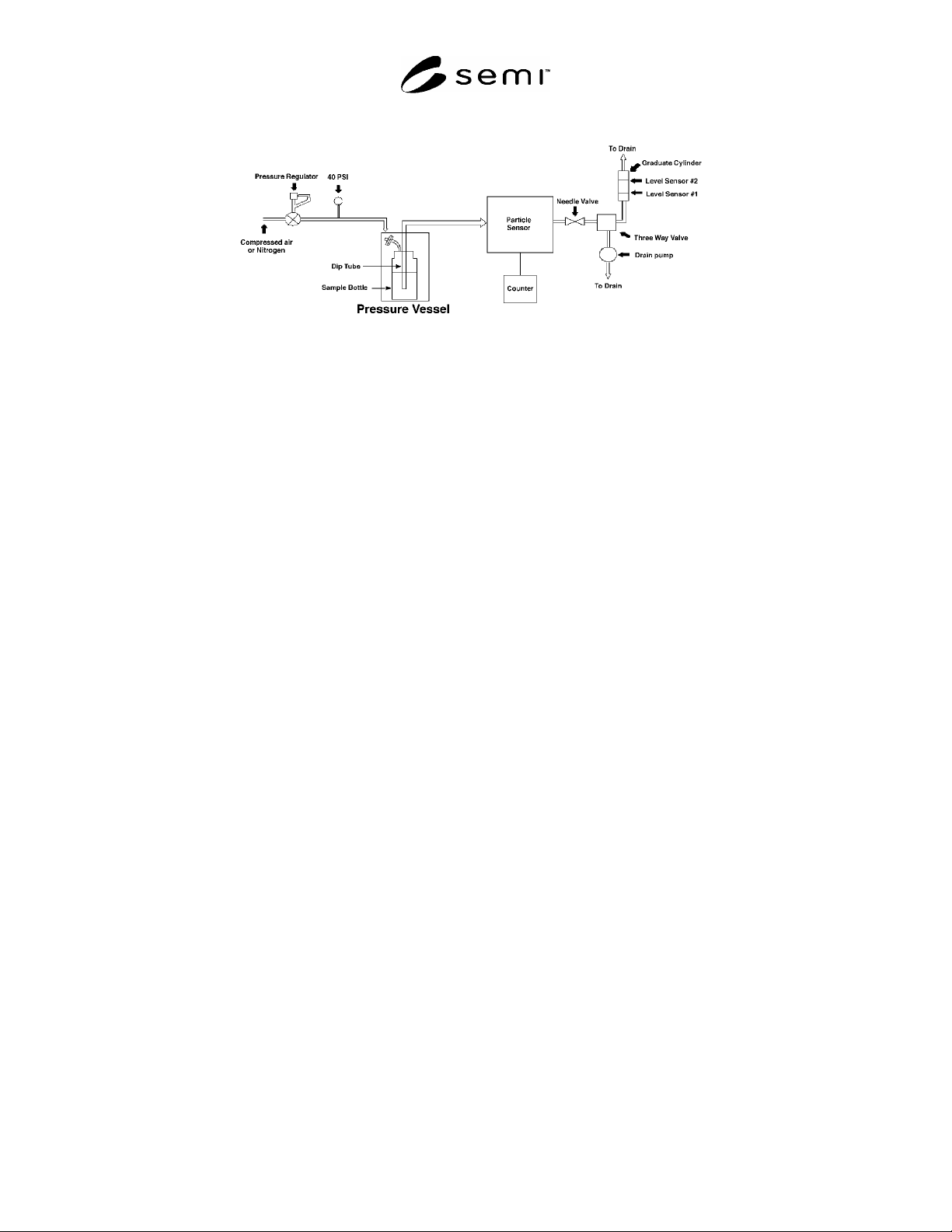
Figure 6
Pressurized Test System
7.14.2.1 The reagent container is placed in a canister suitable for use as a pressure vessel at 4 bar (60 psi), such as a
large steel filter housing. The interior of the canister should be resistant to corrosion by the reagents being tested.
This canister is fitted with a relief valve set at 3.5 bar (50 psi), a nitrogen inlet, and a sealed feed-through for the
sample tube. The reagent container is fitted with a perfluoroalkoxy (PFA) cap to which is attached a hydrophobic
polytetrafluoroethylene (PTFE) nitrogen inlet filter. This permits the nitrogen pressures inside and outside the
reagent container to equilibrate when the vessel is pressurized and prevents particles from the pressure canister from
entering the sample reagent container.
7.14.2.2 Either of two sample and dip tube configurations may be used. In the first, a PFA dip tube, which extends
to 5 cm from the bottom of the reagent container, is attached to the cap. The sample tube, which consists of a single
continuous piece of PFA tubing to reduce the chance of incidental contamination during measurement, is connected
to the cap and the particle counter. This configuration has the advantage that it allows the sample tube to be
disconnected from the cap and dip tube, reducing the risk of splashing and of cross-contaminating samples. The
disadvantage of placing a fitting between the sample and the counter is that the fitting may compromise the integrity
of the sample.
7.14.2.3 In the second configuration, a single tube, without valves, fittings, or discontinuities extends from the
counter, through the cap to 5 cm from the bottom of the reagent container. This has the advantage that it ensures the
integrity of the sample but the disadvantage is that the risk of splashing and cross-contamination is increased.
7.14.3 Particle Counter — Laser light scattering OPCs from any of several suppliers may be used provided they are
in calibration, and used subject to the limitations described in ¶7.14.3.1.
7.14.3.1 Limitations on Counting Particles in Liquid Reagents using OPCs — OPCs are calibrated using
polystyrene latex (PSL) beads suspended in high purity water. The optical properties of naturally occurring particles
in liquid reagents are different from the optical properties of PSL and water. OPCs detect “light-scattering centers”
and calculate particle size and concentration based on the assumption that the light-scattering centers are equivalent
to PSL in water. In reality, light scattered by a particle is dependent upon particle size, particle shape and the
difference between the particle’s refractive index and the refractive index of the surrounding medium. When
properly calibrated OPCs from different manufacturers are used to measure particles in high purity water, they give
comparable size and concentration data.
7.14.3.1.1 Commercially, OPCs are manufactured with different illuminating wavelengths and a variety of optical
arrangements for collecting light scattered by particles. Because of the significant difference in the refractive index
of particles relative to the refractive index of water, the resulting scattered light profile is readily detected by all
OPCs. Hence there is relatively good comparative agreement between OPCs when used to detect particles in high
purity water.
7.14.3.1.2 When calibrated OPCs are used to measure particles in semiconductor liquid reagents, a totally different
situation is encountered. The refractive index of liquid reagents varies significantly from water and is, in general,
greater than water. While the refractive index of reagents is known and can be adjusted for, the refractive index of
particles is unknown and, in many circumstances, is expected to be very close to the refractive index of reagents.

SEMI C1-0705 © SEMI 1978, 2005 25
Particles therefore have a tendency to become invisible to an OPC. The degree of invisibility will depend on the
optical arrangement of each OPC. A study carried out in 1999
8
found that particle concentrations reported by
different sensors varied significantly. Chemical-to-chemical comparison indicated that there was no sensor that
consistently reported higher or lower concentrations than other sensors.
7.14.3.2 Using OPCs in Semiconductor Liquid Reagents — OPCs have a critical role to play in monitoring particles
in liquid reagents. OPCs can detect low concentrations of small particles in real-time and can be easily calibrated
using PSL beads. However, the current state of OPC technology limits their use to claim that a liquid reagent meets
a standard particle concentration at a particular particle size.
7.14.3.2.1 When a supplier of a liquid reagent uses an OPC to specify that reagent’s particle concentration, for
example on a Certificate of Analysis, the make and model of OPC must also be specified. If the customer of the
liquid reagents wishes to check whether the incoming reagent meets the claimed level of cleanliness, the customer
must use an OPC of the same make and model number. However, it has also been shown that even two calibrated
“identical” OPCs can differ by 10–20% when measuring particles in liquid reagents.
7.14.4 Flow Control and Measurement System — A discrete or a continuous method may be used to control and
measure the flow of the sample through the particle counter. In both procedures, a needle valve, downstream of the
counter, is used to control the flow rate. In the discrete procedure, a measured volume of fluid is counted and
collected in a graduated container. Automatic level detection may be used to start and stop the counter. In the
continuous procedure, the flow rate is set and the count is accumulated for a measured time period.
7.14.5 Calibration — Each particle counter (sensor and signal analysis unit) must be calibrated at least once every
twelve months.
7.14.5.1 It is recommended that the calibration be performed by the instrument manufacturer or a metrology
laboratory certified by the instrument manufacturer. Calibration is performed by counting polystyrene latex (PSL)
beads suspended in water. PSL beads of known size (characterized by transmission electron microscopy (TEM) and
concentration (characterized by a scanning electron microscope SEM) must be used. In addition most instrument
manufacturers use a working standard or “gold standard” OPC as a reference against which all OPCs of the same
Model are compared.
7.14.5.2 The determination of size correction factors for particle counters is not recommended. Particle counters
should be calibrated with PSL beads in accordance with the manufacturer’s recommendation.
7.14.6 Coincidence Correction Factors — The determination of coincidence correction factors for particle counters
is not recommended. Particle counters should be calibrated with PSL beads as per the manufacturer’s
recommendation. Coincidence correction factors are only valid for monodispersed concentration of particles.
7.14.7 Efficiency Correction Factors — The determination of efficiency correction factors for particle counters is
not recommended. Particle counters should be calibrated with PSL beads as per the manufacturer’s
recommendation.
7.14.8 Monthly Check — It is desirable to check the OPCs size calibration once a month. PSL beads of known size
and approximate concentration can be purchased from several suppliers. Prepare a stock suspension of a
combination of about 10
7
particles/L of each of the three sizes of PSL beads. Several solutions have been found to
provide acceptably stable suspensions. Among them are: 25:1 ethanol/: water, and water with 0.01% surfactant and
0.05% bactericide. Dilute 10 mL of stock suspension to 1 L and measure the particle concentration using the
procedure specified for reagents. If the results of this check are not within 10% of the expected PSL bead size, the
OPC shall be recalibrated.
7.14.9 Measurement Procedure
7.14.9.1 Setup — Gently invert the sample reagent container three times to homogenize the particle distribution,
then set it aside for 30 minutes to remove the bubbles formed during mixing. Under no circumstances must the
sample reagent container be vigorously shaken or sonicated as this would generate numerous particles.
8 Carrieri, D., D.C.Grant and W.Kelly, “A Comparison of Optical Particle Sensors Used to Measure Particle Concentration in High-Purity
Process Chemicals” Proceedings SEMICON West 1999

SEMI C1-0705 © SEMI 1978, 2005 26
7.14.9.2 The smallest particle counter threshold should deliver at least 50% particle counting efficiency at the
control size limit. The control size limit is the particle size agreed upon between supplier and customer that
represents an acceptable size level. In general this size will be between 0.1 and 0.5 m.
7.14.9.3 Attach the cap with the gas inlet filter and sample tube to the reagent container to be sampled. Place the
reagent container in the canister, and seal the canister so that it may be pressurized. With the sample flow control
valve open, gradually (< 3 bar/min) pressurize the sample to 3 bar for H
2
O
2
and NH
4
OH or as necessary to obtain
the required flow for other fluids. Allow at least 250 mL of the sample to pass through the sensor before counting.
7.14.9.4 For each sample, after 5 aliquots have been measured, perform a chi-squared test to determine if the data
are statistically valid. If the chi-squared test fails, examine the apparatus for defects, such as loose or cracked
fittings, repair as necessary, and repeat the counting of 5 aliquots. If the sample fails both the second and third chi-
squared tests, it is considered to be immeasurable and should be discarded. If a second sample gives similar results,
the apparatus, including the OPC, may be defective and should be checked with a well-characterized sample and
repaired if necessary.
7.14.10 Measurement
7.14.10.1 Discrete Sampling — Measure multiple aliquots of the same sample. The flow rate must be the same as
that at which the instrument was calibrated. The statistical significance of any count data must be taken into
consideration. Some OPCs inspect as little as 1/1000
th
of the available sample flow, and may require a greater
number of aliquots and larger sampling volume to ensure good statistics. For example, to obtain a coefficient of
variation (standard deviation/mean) of 10%, it is necessary that at least 100 particles greater than the control size
limit be counted.
7.14.10.2 Continuous Sampling — If continuous sampling apparatus is being used, adjust the needle valve on the
rotameter to obtain a flow rate consistent with the instrument manufacturer’s recommendations. This flow rate must
be the same as that at which the instrument was calibrated. Correct the indicated value for the effect of the fluid
density and viscosity on the rotameter reading. Allow the first minutes’ fluid to flow to drain, then count the
particles in each of five, 15 second intervals. The statistical significance of any count data must be taken into
consideration. Some OPCs inspect as little as 1/1000
th
of the available sample flow, and may require a greater
number of aliquots and larger sampling volume to ensure good statistics. For example, to obtain a coefficient of
variation (standard deviation/mean) of 10%, it is necessary that at least 100 particles greater than the control size
limit be counted.
7.14.11 Shutdown — As in all portions of this procedure, appropriate safe liquid chemical handling practices must
be used. In particular, attention should be paid to the reactions between different reagents and between reagents and
diluents, including water, and to the inherent hazards of these materials.
7.14.11.1 After the measurement has been completed, vent the pressure vessel to atmospheric pressure through an
appropriate scrubber or exhaust hood, then flush the vessel with nitrogen to remove residual reagent vapors.
7.14.11.2 Flush the OPC and sample system with water or an appropriate solvent to remove the remaining fluid.
7.14.12 Coincidence and Efficiency Corrections — The determination of coincidence and efficiency correction
factors for particle counters is not recommended. If an OPC’s maximum concentration is exceeded, a different OPC
should be selected, or the sample diluted. However any sample dilution will impose additional error and is not
recommended.
7.14.13 Index of Refraction Correction — The determination of an index of refraction correction factor for particle
counters is not recommended, as the refractive index of the contaminating particle is unknown.