semi合集-English.pdf - 第5342页
SEMI M52-0703 © SEMI 2002, 2003 6 6.4.7 In this guid e, a hierarchy of variability levels is used to describe the performance of measurement equipment that is calibrated and adjusted/aligne d accordi ng to the supplier&a…

SEMI M52-0703 © SEMI 2002, 2003 5
5.3.9 level 1 variability (σ
1
) — the variation of
measurement results obtained by repeated
measurements with the same test specimen(s) and the
same measurement tool under nominally identical
conditions without replacing the test specimen between
subsequent measurement runs.
σ
1
tests are performed
with a single calibration in the shortest possible time
interval.
5.3.10 level 2 variability (σ
2
) — the variation of
measurement results obtained by repeated
measurements with the same test specimen(s) and the
same measurement tool with replacing the test
specimen between subsequent measurement runs but
otherwise under nominally identical conditions. σ
2
tests are performed with a single calibration in the
shortest possible time interval.
5.3.11 level 3 variability (σ
3
) — the variation of
measurement results obtained by repeated
measurements with the same test specimen(s) and the
same measurement tool with replacing the test
specimen between subsequent measurement runs but
otherwise under nominally identical conditions. σ
3
tests
are performed over a time period greater than σ
2
tests
without operator induced adjustment.
5.3.12 matching tolerance (∆
m
) — the difference in
bias for any two measurement tools of the same kind.
Otherwise matching tolerance tests are performed under
the conditions of σ
3
tests.
5.3.13 scanning surface inspection system (SSIS) — An
instrument for rapid examination of the entire quality
area on a wafer to detect the presence of localized light
scatterers or haze or both; also called particle counter
and laser surface scanner.
5.3.14 sorting — real and virtual separation of test
specimens in different categories specified by one or
multiple parameters.
6 Recommended Specification for
Measurement Equipment for Silicon Wafers of
the 130-nm Technology Generation
6.1 The recommended specification is structured in
three sections (Tables 1–3):
• Generic Equipment Characteristics (Table 1)
• Materials to be measured (Table 2)
• Metrology Specific Equipment Characteristics
(Table 3)
6.1.1 Tables 1–3 contain the recommended
specifications, referenced documents, test methods, and
comments. Additional explanations and discussions are
provided in this section.
6.2 Generic Equipment Characteristics (Table 1)
6.2.1 The section “Generic Equipment Characteristics”
consists of five subsections:
• Wafer handling
• Reliability
• Procedural
• Documentation
• Computer/User Interface/Connectivity
6.2.2 Subsections covering “Facilities Requirements”
and “Safety/Legal/Regulatory” are not included in the
present guide as these issues are highly user specific
and dependent on national regulations.
6.3 Materials to be measured (Table 2)
6.3.1 Table 2 specifies the parameters of silicon wafers
that the measurement equipment must be capable to
handle and to measure.
6.4 Metrology Specific Equipment Characteristics
(Table 3)
6.4.1 This section specifies the measurement functions
of the SSIS, the setup parameters of the SSIS and the
performance of the SSIS. Specifications in Table 3
apply to wafer front side surface inspection only.
6.4.1.1 For back surface inspection, particles,
scratches, and haze are required to be detected.
6.4.2 The surface defects to be detected by the SSIS
are listed in Table 3, lines 1.1.1 to 1.1.14. They are
reported as LLS or XLS. The measurement
performance of the equipment is verified with PSL
sphere depositions on wafers that meet the COP and
haze requirements of the 130-nm technology
generation.
6.4.3 All size units of LLS are given in [length unit]
LSE, e.g., nm LSE, and refer to a nominal diameter.
6.4.4 The geometrical size of a defect (LLS) may differ
considerably from its size as reported in LSE units, as
the cross section for light scattering of a defect depends
sensitively on the properties of the LLS.
6.4.5 PSL depositions used as reference materials are
required to be CRMs, traceable to a National Standards
Laboratory.
6.4.6 For COPs and particles, classification accuracy
and purity are specified.
SEMI M52-0703 © SEMI 2002, 2003 6
6.4.7 In this guide, a hierarchy of variability levels is used to describe the performance of measurement equipment
that is calibrated and adjusted/aligned according to the supplier's procedures. The various terms are defined in
Section 5. These variability levels are consistent with terms defined in SEMI E89 but not fully interchangeable.
Their relation is indicated in parentheses.
6.4.7.1 Level 1 variability: standard deviation σ
1
(SEMI E89 static repeatability)
6.4.7.2 Level 2 variability: standard deviation σ
2
(SEMI E89 dynamic repeatability)
6.4.7.3 Level 3 variability: standard deviation σ
3
(SEMI E89 reproducibility)
6.4.7.4 In addition two levels of systematic off-set between different tools are defined:
6.4.7.5 Matching tolerance (difference of means ∆
m
)
6.4.7.6 Correlation (regression curve)
6.4.8 Explicitly specified in the present guide is mainly level 3 variability and matching tolerance.
6.4.9 For SSIS, downward compatibility is subject to limitations imposed by changes in geometry and number of
detectors.
6.4.10 For sizing calibration, deposition CRMs are available from a variety of sources. On the other hand, a
reference standard for the defect coordinate performance is not available.
7 Related Documents
7.1 Glossary of Terms Related to Particle Counting and Surface Microroughness of Silicon Wafers,
SEMATECH
Technology Transfer 95082941A-TR
8
7.2 International Technology Roadmap for Semiconductors: 1999 edition
1
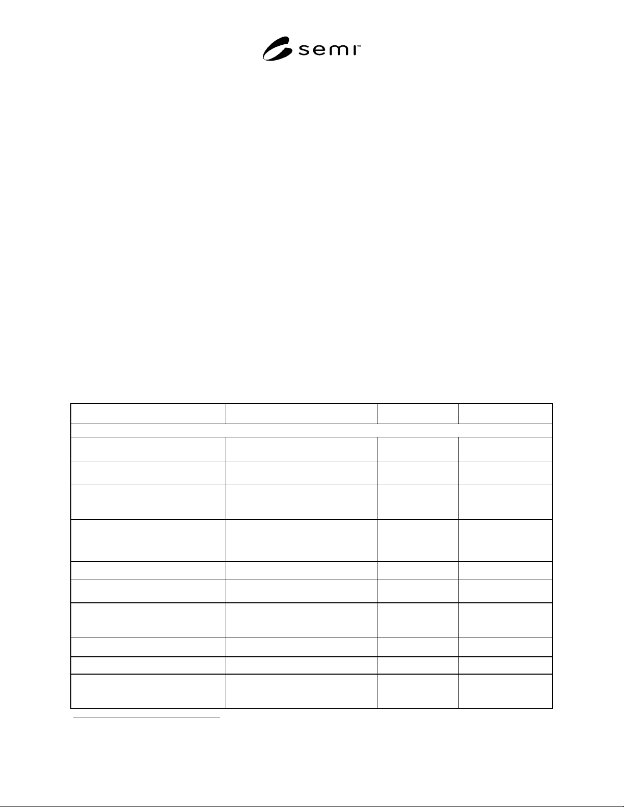
Table 1 Generic Equipment Characteristics
Item Recommended Specification Comment References
1 WAFER HANDLING
1.1 Robot End-Effector
optional wafer edge or backside contact edge as defined by
SEMI M1
1.2 Scan Stage
optional wafer edge or backside contact edge as defined by
SEMI M1
1.3 Wafer Contact Materials
contact materials to leave metals and
organics on wafers less than as defined
in ITRS 99.
1.4 Wafer Detection
protection of accidental contact due to
e.g. cross-slotting double slotting, etc.
1.5 Wafer Rotational Alignment
random in, aligned out
1.6 Number of Cassette Stations
2-4, arbitrary sender/receiver
assignment
1.7 Type of Cassettes
open, FOUP/SMIF, FOSB to be specified
alternatively
SEMI E1.9, SEMI E19,
SEMI E47, SEMI
E47.1, SEMI M31
1.8 Cassette Loading
manual/guided vehicle, conveyor belt
1.9 Automatic Cassette ID
user specific
1.10 Wafer Seating
vertical or off-horizontal during setting
cassette on station
by operator
8 International SEMATECH, 2706 Montopolis Drive, Austin, TX 78741-6499, USA Website: www.sematech.org
SEMI M52-0703 © SEMI 2002, 2003 7
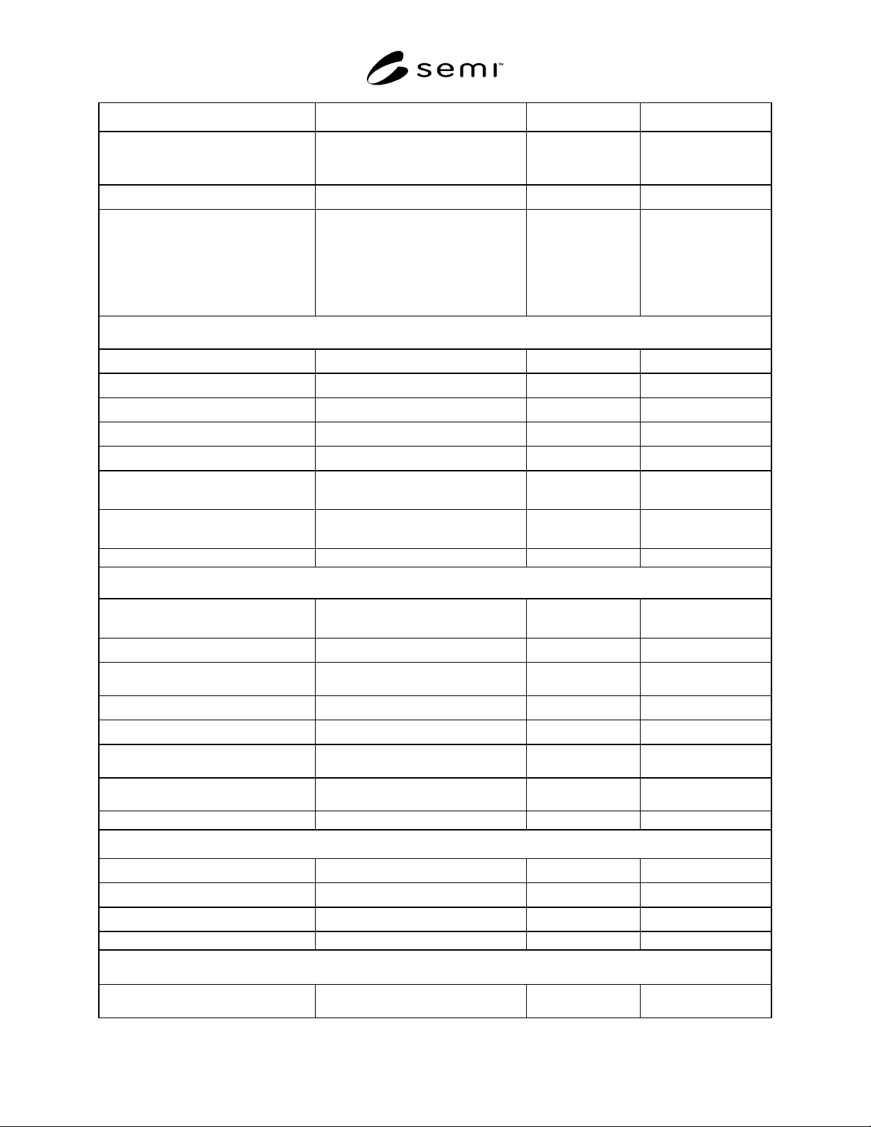
Item Recommended Specification Comment References
1.11 Cassette Filling Modes
random access and loading,
programmable empty slot filling
1.12 Automatic Wafer ID reading
user specific
1.13 Particulate Contamination
front surface: <0.001 PWP per cm
2
,
>90 nm LSE
back surface: <0.001 PWP per cm
2
>120 nm LSE, 0 PWP >250 nm LSE,
0 scratches >120 nm LSE
verify with mirror
polished wafer
surfaces for front
and backside
excluding
contamination from
cassette
2 RELIABILITY
2.1 E-MTBF
p
>2000 h SEMI E10
2.2 E-MTTR
according to service contract SEMI E10
2.3 Equipment Dependent Uptime
>95 % per year SEMI E10
2.4 Response Time
<1 day
2.5 Statistical Process Control (SPC)
performance
automated
2.6 Statistical Process Control (SPC)
machine parameters
automated
3 PROCEDURAL
3.1 Acceptance Testing
user specific
3.2 Transport and Assembly
user specific
3.3 Quality Assurance
supplier conforming with
ISO 9000/9001
ISO9000/9001
3.4 Warranty
>1 year
3.5 Test certificates
user specific
3.6 Spares Availability
>5 years after notification
from supplier
3.7 Change Control
supplier conforming with
ISO 9000/9001
ISO9000/9001
4 DOCUMENTATION
4.1 Installation
required
4.2 Operation
required
4.3 Service
required
5 COMPUTER, USER INTERFACE, CONNECTIVITY
5.1 Computer Operating System
- Microsoft Windows NT 4.0 or higher,
or Unix