semi合集-English.pdf - 第7711页
SEMI T10-0701 © SEMI 2001 4 7 Procedure 7.1 Location and Or ientation of th e Da ta Matri x Symbol 7.1.1 Data Matrix Location Descrip t o r s 7.1.1.1 T he implementation of the sym b o l q uality assessm ent depends on k…
SEMI T10-0701 © SEMI 20013
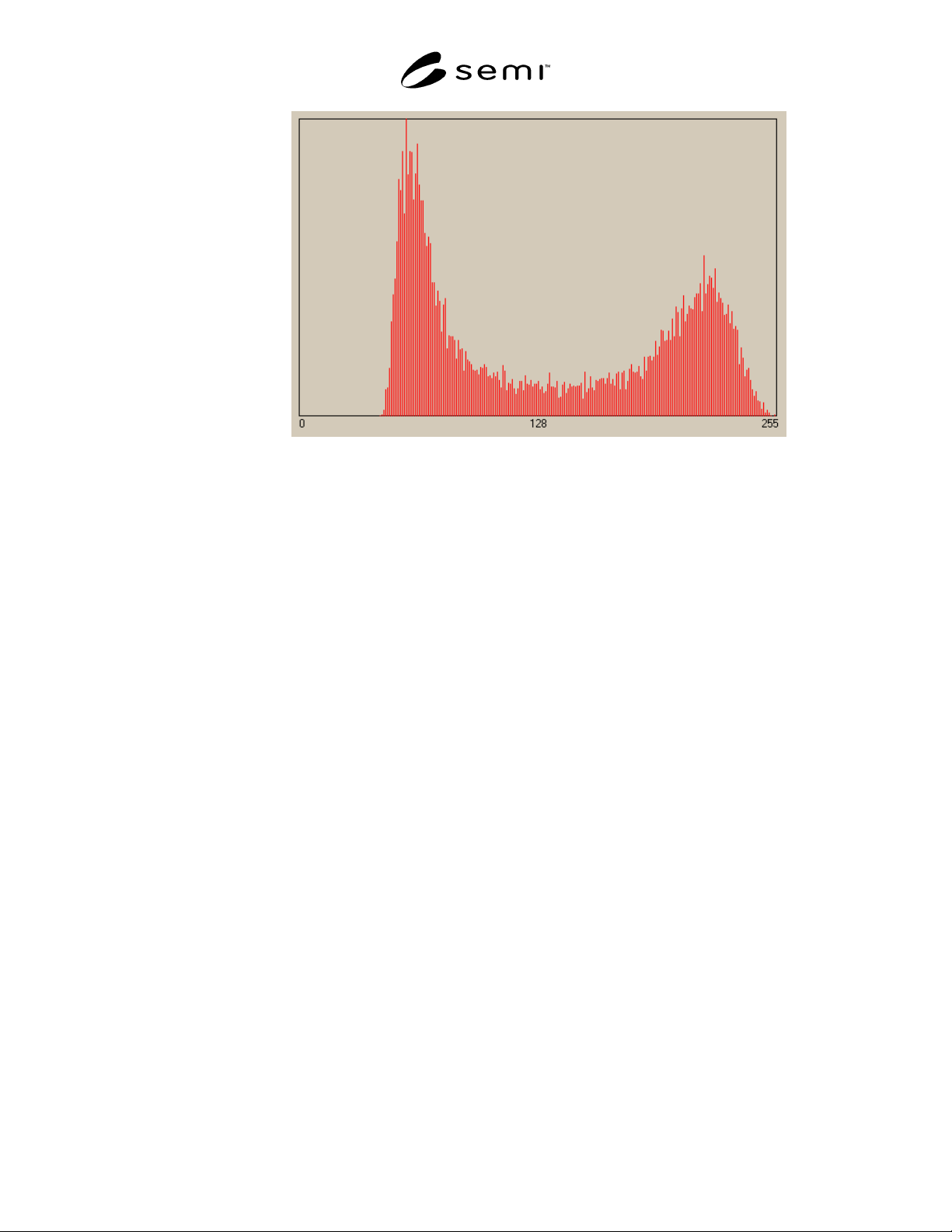
# of Pixels
Grayscale Value
Figure 2
Pixel Histogram
5.1.18 quiet zone areas of space surrounding the
machine-readable symbol. Quiet zone requirements
may be found in application and symbology
specifications. Sometimes called “Clear Area” or
“Margin.”
5.1.19 space
an unmarked cell or area of a Data
Matrix Symbol.
5.1.20 symbol a machine-readable pattern
comprised of a quiet zone, finder pattern, symbology
characters (which include special functions and error
detection and/ or correction characters) required by a
particular symbology.
5.1.21 symbol contrast the difference in grayscale
values between the marked and unmarked areas of a
Data Matrix symbol.
6 Summary of Method and R equirements
6.1 Test Image
6.1.1 A test image of the mark shall be obtained in a
configuration that mimics the typical reading
configuration for that mark, at substantially the same
resolution, illumination, optical focus, image exposure,
gain or other image signal preprocessing settings that
are used during reading. Individual applications may
dictate a specific wavelength or color temperature and
spatial construction of illumination, image resolution,
optical focus, image exposure, etc. The mark/reader
configuration shall be consistent to the extent that
repeatable results can be obtained from a single sample
over many instances of one mark/reader configuration.
6.1.2 The intent of the assessment p rocedure is to
regard a test image from the actual mark/reader
configuration as the source for all assessment.
Therefore, the assessment criteria and the algorithms
used to carry out each assessment should be resident in
the actual reading system or equivalent that is used to
read the mark. If a separate assessment or verification
system, which has different illumination characteristics,
resolution, etc., is used, uncorrelated results may occur.
6.2 Edge Detection Method
6.2.1 Many of the assessment proce dures depend
significantly on the type of edge detection method that
is employed to locate edges in the test image which
define the bounds of the entire Data Matrix symbol as
well as individual cells within the matrix. The edge
detection method used should be consistent throughout
the assessment process.
SEMI T10-0701 © SEMI 2001 4
7 Procedure
7.1 Location and Orientation of the Data Matrix
Symbol
7.1.1 Data Matrix Location Descrip tors
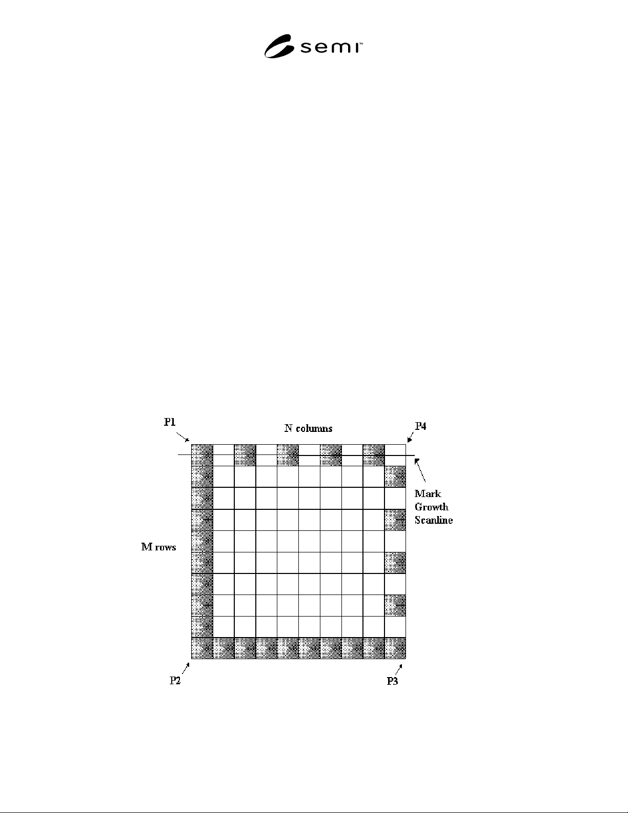
7.1.1.1 The implementation of the symbol quality
assessment depends on knowledge of the location and
orientation of the Data Matrix symbol in the image,
which consists of the 4 image coordinate values of the
matrix corner points, P1, P2, P3, and P4 (see Figure 3).
In addition, the number of rows M and the number of
columns N in the Data Matrix symbol is also required
(see Figure 3). Determine the image coordinate values
and the number of rows and columns using a pre-
processing decoding procedure resident in the reading
system. Should this process either fail or not be
available, determine these values by inspection of the
test image. Report the coordinate values of each matrix
corner point and the number of rows and columns.
7.1.2 The Data Matrix Grid
7.1.2.1 Based on the location of the 4 matrix corner
points and the number of rows and columns in the
matrix establish a geometrical 2 dimensional matrix
grid. Establish line segment P1P2 using points P1 and
P2, line segment P2P3 using P2 and P3, line segment
P3P4 using P3 and P4, and finally line segment P1P4,
using P4 and P1. Divide the number of rows M into the
P1P2 line segment, producing M equally sized line
segments. Divide the number of rows M into the P3P4
line segment producing a similar result. Divide the
number of columns N into P1P4 line segment,
producing N equal sized line segments. Divide the
number of columns N into the P2P3 line segment,
producing a similar result. Connect the corresponding
new line segment endpoints between P1P2 and P3P4.
Connect the corresponding new line segment endpoints
between P1P4 and P2P3. This results in a 2
dimensional matrix grid similar to that shown in Figure
3. This grid is generally quadrilateral in shape,
practically rectangular and ideally square.
7.1.3 Data Matrix Cell Center Point s
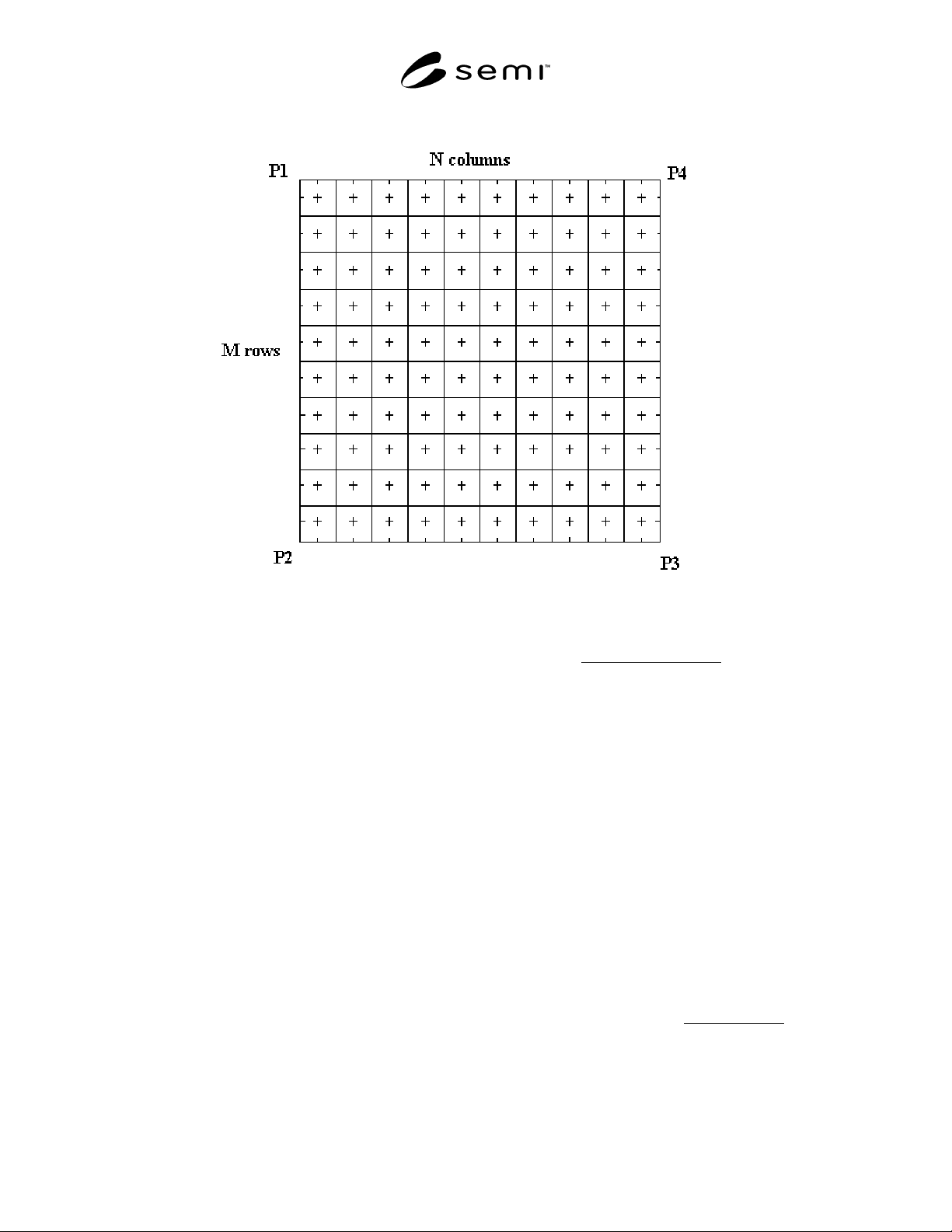
7.1.3.1 Determine the ideal geometric al center points
in each matrix cell in the following manner. Establish a
new set of points at the bisection of each row and
column line segment used to form the matrix grid.
Form line segments between each corresponding row
bisection point in P1P2 and P3P4. Do the same for the
column bisection points in P1P4 and P2P3. The
intersection points between this new set of lines in each
matrix cell is the ideal geometrical matrix cell center
point (see Figure 4).
Figure 3
Data Matrix Corner Points and Mark Growth Scanline
SEMI T10-0701 © SEMI 20015
Figure 4
Matrix Cell Center Locations
7.2 Symbol Contrast
7.2.1 Symbol Contrast measures the distinctiveness of
the two reflective states in the symbol, namely light and
dark. Many aspects of the mark/reader configuration
affect the resulting symbol contrast in the image.
7.2.2 Within the grayscale image, se lect all of the
image pixels, which fall within the area of the symbol,
extending outward to the limits of any required quiet
zones. Sort the selected pixels by their reflectance
values into a histogram. Calculate the arithmetic mean
of the reflectance histogram. Use this mean value to
separate the reflectance histogram into 2 sections or
sub-histograms, which represent approximate
reflectance histograms for the dark and light contrasts
of the symbol. Calculate the arithmetic mean of each
sub-histogram. The lower grayscale value of the two
means represents the dark grayscale value G
D
and the
higher value represents the light grayscale value G
L
.
Use these two grayscale values to calculate a new
symbol contrast. The difference of the grayscale levels
divided by the full range of grayscale (255 in the case
of 8 bit A/D Sampling) is the Symbol Contrast. Report
the Symbol Contrast value.
100%
Range(255)Grayscale
D
G
L
G
SC ×
−
= (1)
7.3
Symbol Contrast Signal to Noi se Ratio (SNR)
7.3.1 The Symbol Contrast Signal to Noise Ratio
(SNR) is a relative measure of the symbol contrast
(signal) to the maximum deviation in the light or dark
grayscale level in the symbol (noise). Using the sub-
histograms and the two grayscale values G
L
and G
D
found in the Symbol Contrast calculation, calculate the
deviation of each sub-histogram about each respective
grayscale value. Two values will result: the deviation
of light pixels D
L
and the deviation of dark pixels D
D
.
Calculate a symbol contrast difference in grayscale
value using the grayscale values. Divide this contrast
difference by the maximum deviation calculated for the
individual light and dark sections of the histogram.
This ratio is the Symbol Contrast SNR. Report the
symbol contrast SNR.
()
D
D,
L
DMax
D
G
L
G
SNRContrastSymbol
−
= (2)