semi合集-English.pdf - 第2652页
SEMI E95-1101 © SEMI 2000 , 2001 7 Tit le Panel In fo r m a ti o n P an e l Comma nd Panel N avig atio n Panel Figure 8 Basic Layou t 5.3.6.2 All the panel s are tiled edge to edge to create the display, and only the rel…
SEMI E95-1101 © SEMI 2000, 2001 6
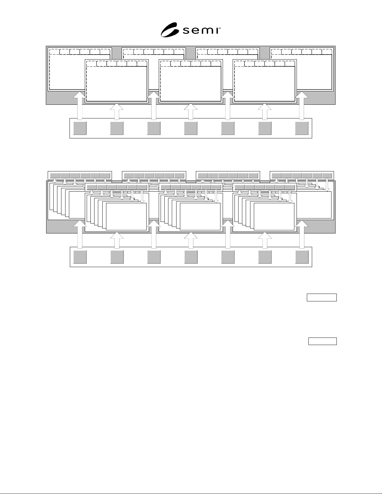
Jobs System Recipes Setup (Future) Alarms Help
View 6View 5View 4View 3View 2View 1 View 6View 5View 4View 3View 2View 1 View 6View 5View 4View 3View 2View 1 View 6View 5View 4View 3View 2View 1
View 6View 5View 4View 3View 2View 1 View 6View 5View 4View 3View 2View 1 View 6View 5View 4View 3View 2View 1
Information
Panel
Functional
Areas
Figure 6
Network Navigation Model — Tab Sub-navigation
Jobs System Recipes Setup (Future) Alarms Help
View 1 View 2 View 3 View 4 View 5 View 6 View 1 View 2 View 3 View 4 View 5 View 6 View 1 View 2 View 3 View 4 View 5 View 6
Information
Panel
Functional
Areas
View 1 View 2 View 3 View 4 View 5 View 6
View 6View 5View 4View 3View 2View 1View 6View 5View 4View 3View 2View 1 View 6View 5View 4View 3View 2View 1
Sub-navigation Buttons
Figure 7
Network Navigation Model — Button Sub-navigation
5.3.5 Display Layout Description
5.3.5.1 The display layout is designed for ease of use with touchscreen input devices and does not require a
keyboard or other pointing device. By dividing the screen into rectangular panels, provision is made to
accommodate the display and input of information organized by the tasks users must accomplish in managing and
monitoring processing, maintaining and repairing the equipment, and other relevant work.
5.3.6 Basic Layout Mandatory
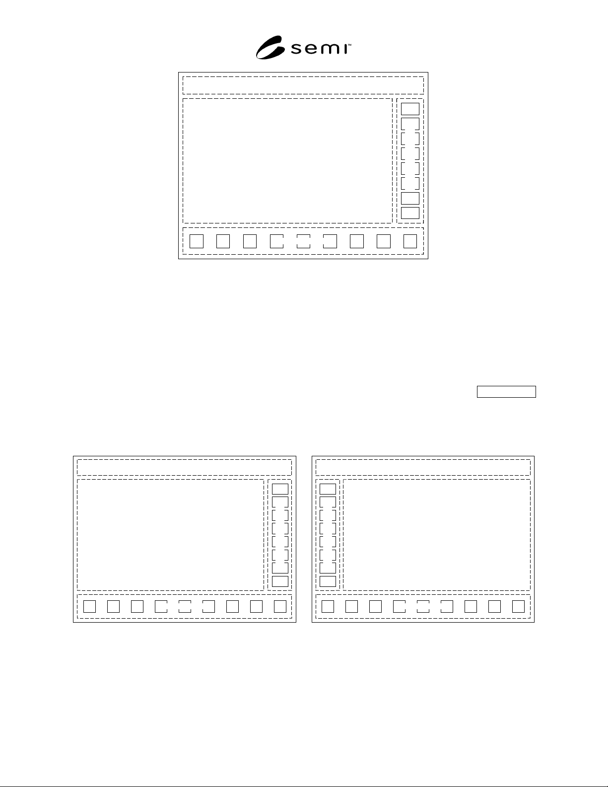
5.3.6.1 The basic layout shall contain four panels as shown and oriented in Figure 8. At a minimum, the interface
shall support the orientation of the command panel on the right-hand side, unless the enhanced layout (Section 5.3.7)
is implemented.
SEMI E95-1101 © SEMI 2000, 20017
Title Panel
Information Panel
Command Panel
N
avigation Panel
Figure 8
Basic Layout
5.3.6.2 All the panels are tiled edge to edge to create the display, and only the relative position of the panels is
specified in this standard. Panels may or may not display a visible border. For an interface that is the primary display
(typically, but not always at the front of equipment), an outer window frame allowing window resizing, closing, or
positioning shall not be shown or enabled. This is to prevent the user from mistakenly “losing” the window, which
may result in a dangerous condition. If desired, a logged-in user with sufficient privileges may be allowed to resize,
but not minimize or close, the primary display window. Secondary instances of the interface (e.g., displayed at a
maintenance node or displayed at a remote node) may show and enable the outer window frame.
5.3.7 Enhanced Layout Recommended
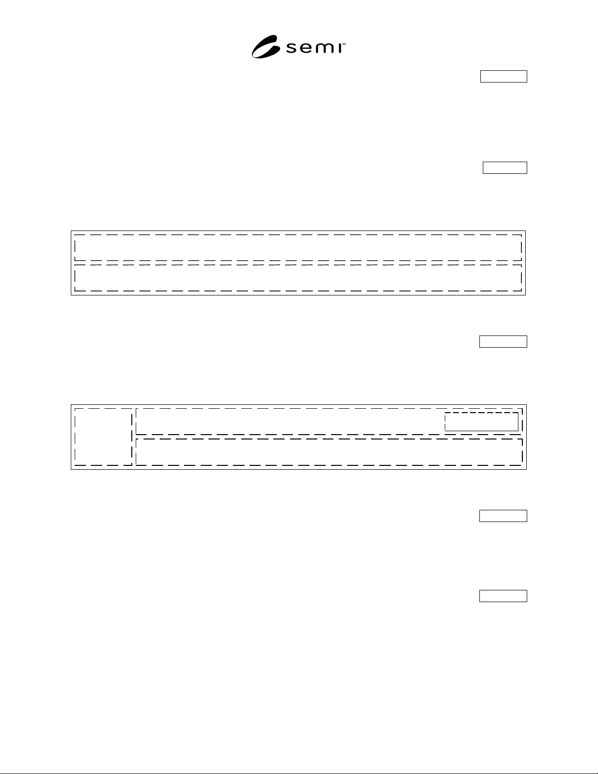
5.3.7.1 It is strongly recommended that left-handed users be allowed to change the location of the command panel
to the left-hand side (see Figure 9(b)) to avoid obscuring the screen when reaching with their left hand to make
selections on the command panel when it is located on the right-hand side of the screen.
Title Panel
Information Panel
Command Panel
N
avigation Panel
Title Panel
Information Panel
Command Panel
N
avigation Panel
(a) (b)
Figure 9
Enhanced Layout – Right and Left Command Panel Orientation
SEMI E95-1101 © SEMI 2000, 2001 8
5.3.8 Title Panel Description
5.3.8.1 The title panel is a horizontal area above the information and command panels, at the top of the interface
window. It is always displayed and contains the host communications status display (if host communications is
supported), date/time display, Login/Logout button (if security is supported), message display area, and the name of
the current view. It may optionally contain a corporate identifier or logo, a display of critical parameters, an audible
alarm silencing button, orientation graphics, a light tower representation, and other items that should always be
displayed to ensure effective operation.
5.3.9 Title Panel Basic Information Mandatory
5.3.9.1 Shown below is the title panel with the mandatory display objects. The relative positions shown, with the
top portion of the title panel containing the date/time display at the left, the current view name to its right, and with
the message area below the top portion, are mandatory.
Date/Time
Display
Message Area
Current View Name
Figure 10
Title Panel
5.3.10 Title Panel with Conditional Information Conditional
5.3.10.1 Shown below is the title panel with the mandatory display objects, plus the conditional host
communications status display and the conditional Login/Logout button. The relative positions shown, with the host
communications status display left-most, and the Login/Logout button at the upper right, are mandatory.
Host
Communication
Status
Login Here
Date/Time
Display
Message Area
Current View Name
Figure 11
Title Panel
5.3.10.2 Title Panel Host Communications Status Conditional
5.3.10.2.1 If the equipment supports host communication then status information shall be included in the title panel.
Information such as communications status (i.e., whether communications is active), communications state (i.e.,
connected, disconnected, etc.), and whether the equipment is in a local or remote mode may be displayed here. The
display of specific information is dependent on the host communication protocol which may impose additional
specific requirements on what is displayed.
5.3.10.3 Title Panel Login/Logout Button Conditional
5.3.10.3.1 The Login/Logout button label reads “Login Here” until a user is logged in, then displays a user
identifier until the user logs out. User selection of the Login/Logout button invokes a dialog box where the user may
enter a user identifier and password, or, if already logged in, may select a button to log out. If required by the
implementation, when this dialog box is displayed, all other functions in the interface window may be disabled,
including the navigation panel.