semi合集-English.pdf - 第2253页
SEMI E58-0703 © SEMI 1997, 2003 34 15 ARAMS States for Multi-Module Equipment 4.3 The preceding sect ions defin e how ARAM S is to be supported by simple equipm ent. Simple equi pment includes equip ment with at m o st o…
SEMI E58-0703 © SEMI 1997, 2003 33
Table 15 Table 15 Section References for Additional ARAMS Capabilities
Capability Section Reference
User-Configurable Powerup State ARAMS 11.4.4, 16.3.2
User-Configurable Fault Recovery ARAMS 11.4.2, 11.4.5, 11.4.6, 16.8.2
Accumulator Data ARAMS 11.5, 15.5
User-Generated ARAMS Substate Table(s) ARAMS 10.1, 10.2, 10.3, 14.3, 15.3
Equipment-Generated ARAMS Substate Table(s) ARAMS 10.1, 10.2, 10.3, 15.4
User-Generated ARAMS Symptom Table(s) ARAMS 10.1, 10.2, 10.4, 14.3, 14.4, 15.3
Human Interface Requirements ARAMS 14.2, 14.3, 14.4, 14.5
Equipment-Selected Substates ARAMS 11.4.7, 16.6
User-Configurable Fault Detection in ENGINEERING ARAMS 11.4.1, 16.7, 16.7.4
User-Configurable Fault Recovery to ENGINEERING ARAMS 11.4.2, 16.8
Human Interface Requirements ARAMS 14, 14.1, 14.2.
14.1.25 Human Interface Requirements — Operator access to ARAMS data and state change, defined in Sections
14, 14.1, and 14.2.
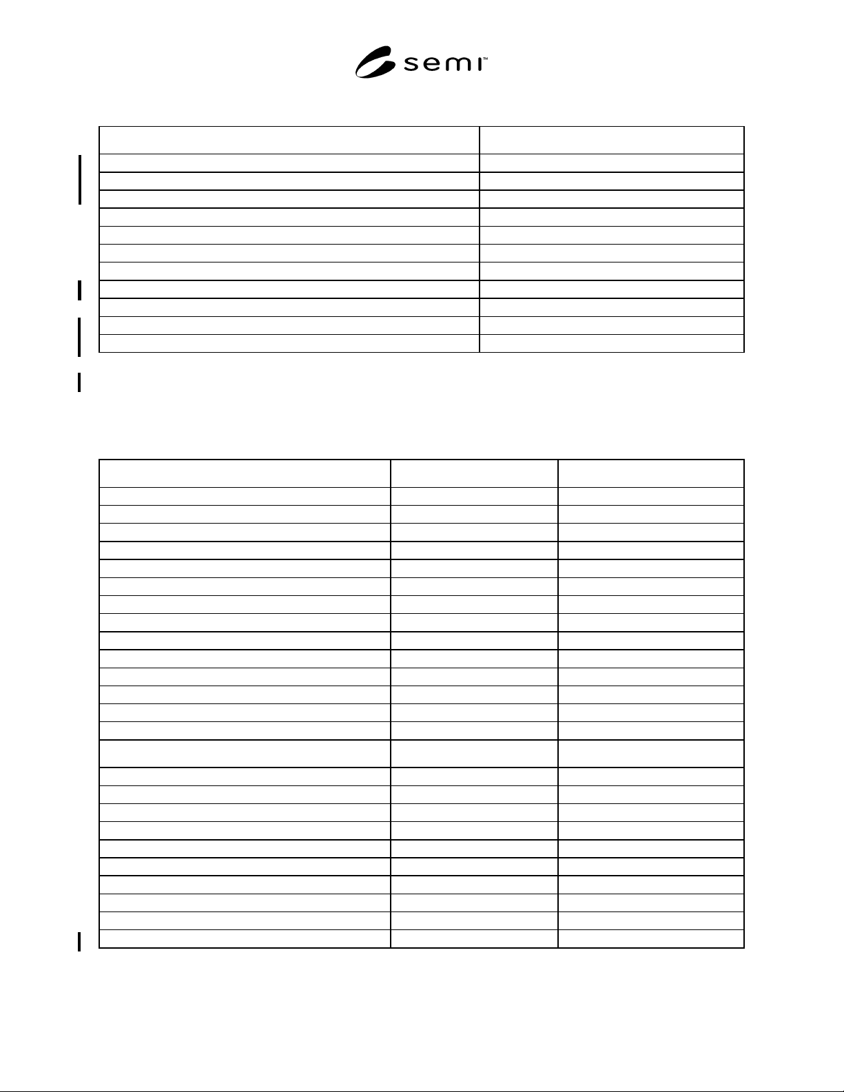
14.2 Requirements for Compliance — Table 16 provides a checklist for ARAMS compliance.
Table 16 Table 16 ARAMS Compliance Statement
Fundamental ARAMS Requirements Implemented ARAMS Compliant (See NOTE 1.)
Event Notification ❏ Yes ❏ No ❏ Yes ❏ No
Clock Services ❏ Yes ❏ No ❏ Yes ❏ No
Read-Only Data Access ❏ Yes ❏ No ❏ Yes ❏ No
User-Configurable Data Access ❏ Yes ❏ No ❏ Yes ❏ No
Alarm/Exception Management ❏ Yes ❏ No ❏ Yes ❏ No
ARAMS State Model ❏ Yes ❏ No ❏ Yes ❏ No
ARAMS State Transition Notification ❏ Yes ❏ No ❏ Yes ❏ No
ARAMS Substate Codes ❏ Yes ❏ No ❏ Yes ❏ No
ARAMS Status Data ❏ Yes ❏ No ❏ Yes ❏ No
ARAMS Constant Data ❏ Yes ❏ No ❏ Yes ❏ No
ARAMS Event Report Data ❏ Yes ❏ No ❏ Yes ❏ No
Host State Change Request ❏ Yes ❏ No ❏ Yes ❏ No
Estimation of Powerdown Time ❏ Yes ❏ No ❏ Yes ❏ No
ARAMS Behavioral Requirements ❏ Yes ❏ No ❏ Yes ❏ No
Additional Capabilities Implemented ARAMS Compliant (See NOTE 2.)
User-Configurable Powerup State ❏ Yes ❏ No ❏ Yes ❏ No
User-Configurable Fault Recovery to Manufacturing ❏ Yes ❏ No ❏ Yes ❏ No
Accumulator Data ❏ Yes ❏ No ❏ Yes ❏ No
User-Generated ARAMS Substate Table(s) ❏ Yes ❏ No ❏ Yes ❏ No
Equipment-Generated ARAMS Substate Table(s) ❏ Yes ❏ No ❏ Yes ❏ No
User-Generated ARAMS Symptom Table(s) ❏ Yes ❏ No ❏ Yes ❏ No
Equipment-Selected Substates ❏ Yes ❏ No ❏ Yes ❏ No
User-Configurable Fault Detection in ENGINEERING ❏ Yes ❏ No ❏ Yes ❏ No
User-Configurable Fault Recovery to ENGINEERING ❏ Yes ❏ No ❏ Yes ❏ No
Human Interface Requirements ❏ Yes ❏ No ❏ Yes ❏ No
NOTE 1: Do not mark YES unless all fundamental ARAMS requirements are implemented.
NOTE 2: Additional capabilities may not be marked ARAMS-compliant unless all fundamental ARAMS requirements are implemented.

SEMI E58-0703 © SEMI 1997, 2003
34
15 ARAMS States for Multi-Module Equipment
4.3 The preceding sections define how ARAMS is to
be supported by simple equipment. Simple equipment
includes equipment with at most one process chamber,
and a single process capability, where individual
modules are not treated separately from the equipment.
NOTE 22: Process capability, in this context, refers to the
factory’s manufacturing process. Equipment with more than
one process capability may be used in different ways at
different steps, typically through different process recipes.
Such equipment may be “available” for one process but not
for another. This type of complexity is neither addressed nor
affected by SEMI E10 or by ARAMS.
4.4 This section addresses the application of ARAMS
to complex equipment, including modular equipment
where individual modules may be in different ARAMS
states/substates. Complex equipment includes cluster
tools and any other type of equipment that is organized
into separate subsystems that can be addressed
individually. In this case, it is advantageous for each
module or subsystem to be given its own ARAMS state
model. In addition, the overall equipment system itself
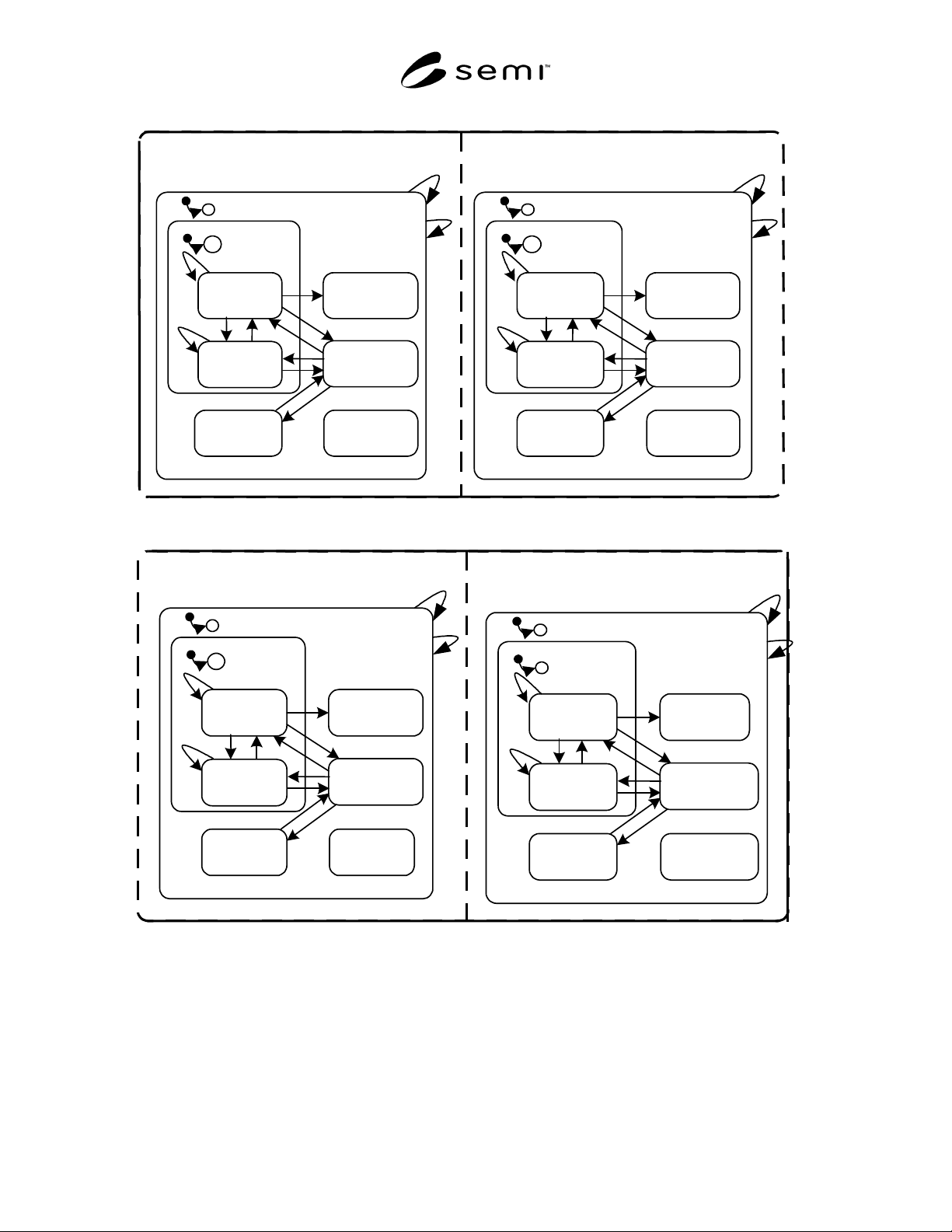
has an ARAMS state model. This situation is illustrated
in Figure 6.
4.5 The complexities of possible interactions between
ARAMS states of the individual modules and the
ARAMS state of the cluster tool as a whole are beyond
the scope of this document. The following approach is
recommended:
• Each module complies to fundamental
requirements for the ARAMS state model, data
variables, and message services.
• The integrated cluster tool complies to
requirements for the ARAMS state model, data
variables, and message services.
• The set of all the ARAMS models above are
simultaneously active, as represented in Figure 6.
• The relationships between the ARAMS state for
the cluster tool and the ARAMS states for the
individual modules are user-configurable wherever
possible. (Certain relationships between the cluster
and critical modules, such as central wafer handler
or central load lock, may not be configurable: e.g.,
if the critical module is down, the cluster is down.)
SEMI E58-0703 © SEMI 1997, 2003 35
PROCESS MODULE 1
PROCESS MODULE 2
10
MANUFACTURING
TOTAL TIME
SCHEDULED
DOWNTIME
UNSCHEDULED
DOWNTIME
NON-
SCHEDULED
TIME
STANDBY
PRODUCTIVE
ENGINEERING
11
4
3
13
C
1
C
2
12
7
8
15
14
9
5
6
10
MANUFACTURING
TOTAL TIME
SCHEDULED
DOWNTIME
UNSCHEDULED
DOWNTIME
NON-
SCHEDULED
TIME
STANDBY
PRODUCTIVE
ENGINEERING
11
4
3
13
C
1
C
2
12
7
8
15
14
9
5
6
CLUSTER
TRANSPORT MODULE
10
MANUFACTURING
TOTAL TIME
SCHEDULED
DOWNTIME
UNSCHEDULED
DOWNTIME
NON-
SCHEDULED
TIME
STANDBY
PRODUCTIVE
ENGINEERING
11
4
3
13
C
1
C
2
12
7
8
15
14
9
5
6
10
MANUFACTURING
TOTAL TIME
SCHEDULED
DOWNTIME
UNSCHEDULED
DOWNTIME
NON-
SCHEDULED
TIME
STANDBY
PRODUCTIVE
ENGINEERING
11
4
3
13
C
1
C
2
12
7
8
15
14
9
5
6
Figure 6
ARAMS Model for Cluster