semi合集-English.pdf - 第296页
SEMI E47.1-0305 © SEMI 1997, 2005 11 y242 150 y243 (See Table1 ) FACIAL DAT UM PLANE x56=1 94. 75 [ 204 . 75] ± 0 . 2 5 (a t b o tto m r a i l ) x53 195 [ 205] ( el s e w her e) x57 18 0 OPTI ONAL FRON T CONVEYOR…
SEMI E47.1-0305 © SEMI 1997, 2005 10
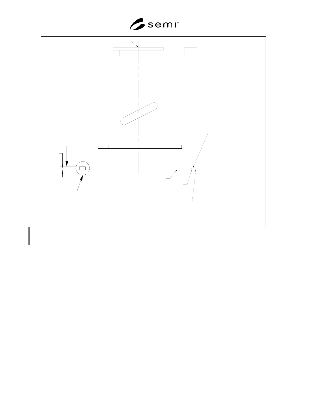
HORIZONTAL DATUM PLANE
z43=2±1
FACIAL DATUM PLANE
FOUP BOTTOM
SURFACE
THEORETICALLY POSSIBLE PROTRUSION
RESULTING FROM TOLERANCE
DIFFERENCE BETWEEN
E47.1 AND E62
OPTIONAL FRONT CONVEYOR
SURFACE
(MUST BE COPLANAR WITH THE
BOTTOM OF THE FRONT SEAL ZONE
OR FARTHER FROM THE HDP THAN
THE BOTTOM OF THE FRONT SEAL
ZONE. THE OPTIONAL FRONT
CONVEYOR SURFACE MUST BE
COPLANAR WITH THE SIDE
CONVEYOR RAILS.)
z316
7.0
Optional Conveyo
r
Feature Placement
Volume
COPLANAR WITH THE LEFT AND
RIGHT BOTTOM CONVEYOR
RAILS.)
Figure 13
Side View of FOUP Showing Optional Front Conveyor Surface Feature
SEMI E47.1-0305 © SEMI 1997, 2005 11
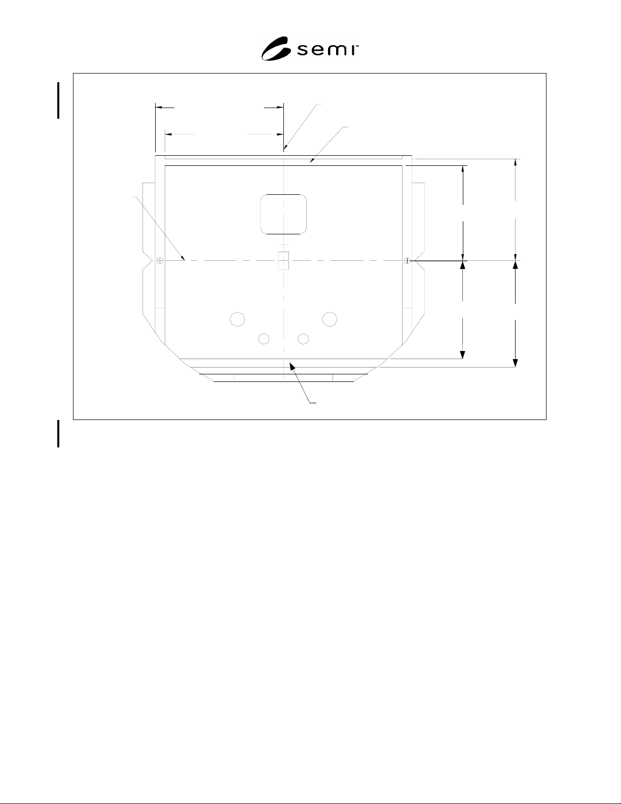
y242
150
y243
(See Table1 )
FACIAL DATUM
PLANE
x56=194.75 [204.75] ±0.25
(at bottom rail)
x53195 [205]
(elsewhere)
x57180
OPTIONAL FRONT
CONVEYOR SURFACE
FEATURE
BILATERAL DATUM PLANE
y244
155.0
y245
169.0
OPTIONAL CONVEYOR FEATURE
PLACEMENT VOLUME
Figure 14
Bottom View of FOUP Showing Optional Conveyor Features
x56 = 194.75± 0.25
(at bottom rail)
x53 ≤ 195
(elsewhere)
x57 ≤ 180
SEMI E47.1-0305 © SEMI 1997, 2005 12
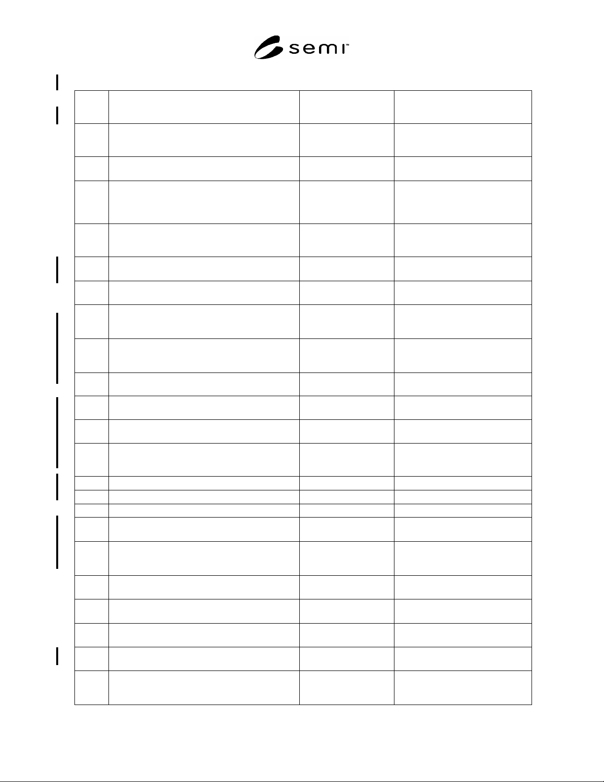
Table 1 Dimensions for FOUP
Symbol
Used
Value Specified
Datum
Measured From
Feature Measured To
‡ 60° bilateral datum plane center line of the right and left
kinematic grooves in the top robotic
handling flange
45 ± 1° nominal wafer center line surface of the center hole in the top
robotic handling flange
‡ 52 ± 1° bilateral datum plane or
vertical plane rotated
away from it about
nominal wafer center line
angled surface of the kinematic
grooves in the top robotic handling
flange
‡
45 ± 0.5° either vertical datum
plane
sides of notches in the top robotic
handling flange and in the side fork-
lift flanges
30 ± 0.5° horizontal line on
bilateral datum plane
ramp of front retaining feature
d63 35 ± 0.1 mm
(1.378 ± 0.004 in.)
diameter centered on the
nominal wafer center line
sides the center hole in the top robotic
handling flange at height z47
d65 10 ± 0.5 mm
(0.39 ± 0.02 in.)
diameter centered on the
intersection of x65 and
the facial datum plane
surface of cylindrical fork-lift pin
holes in left and right bottom
conveyor rails
f60 175 N (39.3 lbf.) minimum not applicable force in any direction which both
retaining features are able to
withstand
r59‡ 6 mm (0.24 in.) maximum not applicable radius on peak of kinematic grooves
in the top robotic handling flange
r60 16 ± 0.5 mm
(0.63 ± 0.02 in.)
nominal wafer center line ends of slot for center retaining
feature
r61 16 mm (0.63 in.) minimum nominal wafer center line walls of chamber above slot in center
retaining feature
r63‡ 66 mm (2.60 in.) maximum nominal wafer center line near end of the right and left
kinematic grooves in the top robotic
handling flange
r64 9.5 mm (0.37 in.) maximum not applicable corners of front retaining feature
r65 1 mm (0.04 in.) maximum not applicable all concave features (radius)
r66 2 mm (0.08 in.) maximum not applicable all required convex features (radius)
r67 240 mm (9.45 in.) maximum y67 in front of nominal
wafer center line
any part of FOUP
r69 10 mm (0.4 in.) minimum (required)
15 mm (0.6 in.)
(recommended for ergonomic reasons)
not applicable correctable FOUP misalignment in
any horizontal direction
x41 30 ± 1 mm (1.18 ± 0.04 in.) bilateral datum plane front right orientation notch on
robotic handling flange
x42 50 ± 1 mm (1.97 ± 0.04 in.) bilateral datum plane front left orientation notch on robotic
handling flange
x43 50 ± 1 mm (1.97 ± 0.04 in.) bilateral datum plane rear orientation notch on robotic
handling flange
x44 53 mm (2.09 in.) maximum bilateral datum plane encroachment of FOUP underneath
robotic handling flange
x45 65.3 ± 1 mm (2.57 ± 0.04 in.) bilateral datum plane nearest point of side position and
orientation notches on robotic
handling flange