semi合集-English.pdf - 第4707页
SEMI C3.22-1000 © SEMI 1983, 2004 2 4.2.2.4 Temperatures: Detector 200°C Column Oven 21°C 4.2.3 Calibrati on Standard — 100 ppm (mole/mole) nitrogen in oxygen. 4.2.4 Operating Procedure 4.2.4.1 Inj ect the calibration st…
SEMI C3.22-1000 © SEMI 1983, 2004 1
SEMI C3.22-1000 (Withdrawn 1104)
STANDARD FOR OXYGEN (O
2
), 99.5% QUALITY
This standard was technically approved by the Global Gases Committee and is the direct responsibility of the
North American Gases Committee. Current edition approved by the North American Regional Standards
Committee on July 11, 2004. Initially available at www.semi.org September 2004; to be published
November 2004. Originally published in 1983; previously published in 1993.
NOTICE: This document was balloted and approved
for withdrawal in 2004.
1 Description
1.1 Oxygen is a colorless, odorless and oxidizing gas.
It supports combustion.
2 Specifications
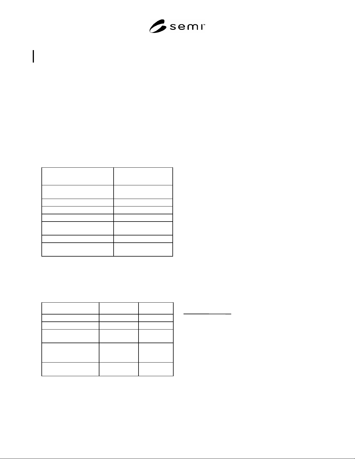
ASSAY: 99.5%
Impurities Maximum Acceptable
Level (ppm)*
Carbon monoxide and Carbon
dioxide (CO + CO
2
)
5
Nitrogen (N
2
) 100
Nitrous oxide (N
2
O) 2
Particles **
Total Hydrocarbons expressed as
Methane (THC)
25
Water (H
2
O) (v/v) 1
TOTAL IMPURITIES
INCLUDING RARE GASES
5,000
* An analysis of significant figures has not been considered. The
number of significant figures will be based on analytical accuracy and
the precision of the provided procedure.
** To be determined between supplier and user.
3 Physical Constants (for information only)
Metric Units US Units
Molecular weight 31.999 31.999
Boiling point at 1 atm -183°C -297.4°F
Density of gas at 25°C
(77°F) and 1 atm
1.309 kg/m
3
0.082 lb/ft
3
Specific gravity of gas at
21.1°C (70°F) and 1 atm
(air = 1)
1.1049 1.1049
Density of liquid at
boiling point
1142 kg/m
3
71.27 lb/ft
3
4 Analytical Procedures
4.1 Carbon Monoxide, Carbon Dioxide, and Nitrous
Oxide — This procedure is for the determination of
carbon monoxide, carbon dioxide and nitrous oxide in
oxygen using infrared spectrophotometry.
4.1.1 Detection Limits — 0.5 ppm (mole/mole) carbon
monoxide, 0.1 ppm (mole/mole) carbon dioxide, and
0.2 ppm (mole/mole) nitrous oxide.
4.1.2 Instrument Parameters
4.1.2.1 10 meter variable path infrared gas cell.
4.1.2.2 Grating infrared spectrophotometer.
4.1.2.3 Bourdon Vacuum Gauge.
4.1.3 Calibration Standards — 10 ppm (mole/mole)
carbon monoxide, 10 ppm (mole/mole) carbon dioxide
and 10 ppm (mole/mole) nitrous oxide, balance oxygen.
4.1.4 Operating Procedure
4.1.4.1 Pressurize the evacuated gas cell to 50 psia
with the calibration standard. Scan the following wave
numbers for absorbance: carbon monoxide 2172 cm
-1
,
nitrous oxide 2235 cm
-1
, and carbon dioxide 2360 cm
-1
.
4.1.4.2 Evacuate the cell and pressurize to 50 psia
with the oxygen sample. Scan the appropriate wave
numbers as in 4.1.4.1.
4.1.4.3 Compare the absorbance of the calibration
standard to that of the oxygen sample being tested.
Calculate the concentrations of carbon monoxide,
carbon dioxide and nitrous oxide, using the formula
below. The results may not exceed the specifications in
Section 2 of this Standard.
Sample Absorbance
Standard Absorbance
Concentration
of Standard
Concentration
of Sample
4.2 Nitrogen — This procedure is for the
determination of nitrogen in oxygen using a gas
chromatograph with a thermal conductivity detector.
4.2.1 Detection Limit — 10 ppm (mole/mole).
4.2.2 Instrument Parameters
4.2.2.1 Column: 5A molecular sieve, 4.6 m (15 ft) by
3.2 mm (1/8 in) ss or equivalent.
4.2.2.2 Carrier Flow: 30 mL/min helium.
4.2.2.3 Sample Volume: 2.0 mL.

SEMI C3.22-1000 © SEMI 1983, 2004 2
4.2.2.4 Temperatures:
Detector 200°C
Column Oven 21°C
4.2.3 Calibration Standard — 100 ppm (mole/mole)
nitrogen in oxygen.
4.2.4 Operating Procedure
4.2.4.1 Inject the calibration standard into the column
using a gas sampling valve. Record the retention time
and peak area.
4.2.4.2 Inject the sample to be tested in same manner
as the calibration standard. Record the retention time
and peak area.
4.2.4.3 Repeat 4.2.4.1.
4.2.4.4 Compare the average peak area of the
calibration standard to that of the oxygen sample being
tested. Calculate the concentration of nitrogen, using
the formula below. The result may not exceed the
specification in Section 2 of this Standard.
Sample Peak Area
Standard Peak Area
Concentration
of Standard
Concentration
of Sample
4.3 Total Hydrocarbons — This procedure is for the
determination of total hydrocarbons in oxygen using a
continuous flow flame ionization detector equipped
total hydrocarbon analyzer. (See Notes 1, 2, 3.)
4.3.1 Detection Limit — 0.1 ppm (mole/mole).
4.3.2 Flow Requirements
4.3.2.1 High purity, hydrocarbon-free (less than 1.0
ppm) hydrogen: 35–40 mL/min or 40% hydrogen in
either helium or nitrogen matrix at 75–80 mL/min.
4.3.2.2 Dry, hydrocarbon-free (less than 1.0 ppm) air:
350–400 mL/min.
4.3.2.3 Set sample flow rates in accordance with the
instrument manufacturer’s instructions.
4.3.3 Calibration Standards
4.3.3.1 Zero oxygen with known quantity of
hydrocarbons at 0.5 ppm level.
4.3.3.2 The upper level span gas not exceeding 4 times
the concentration of the specification.
4.3.4 Operating Procedure
4.3.4.1 Do not change the flow settings for hydrogen,
air, and sample once established.
4.3.4.2 Introduce the zero oxygen with known
quantity of hydrocarbons and, using the 0–10 ppm
range, set the needle (or output) to read the correct level
using the zero adjust knob.
4.3.4.3 Introduce the span gas standard in oxygen and,
using the span adjust knob, set the needle (or output
reading) to match the level of hydrocarbons in the span
gas.
4.3.4.4 Introduce oxygen sample into the analyzer and
read the quantity of hydrocarbons on the analyzer
meter. The result may not exceed the specification in
Section 2 of this Standard.
4.4 Water — This procedure is for the determination
of trace moisture (water) in oxygen using a continuous
flowing, cooled-surface condensation, dewpoint/frost-
point hygrometer. (See Notes 4, 5, 6.)
4.4.1 Detection Limit — 0.6 ppm (vol/vol) at -79°C (-
100°F).
4.4.2 Flow Requirements
4.4.2.1 Set sample flow rate and pressure in
accordance with the instrument manufacturer’s
instructions.
4.4.2.2 Gas must flow past the chilled mirror where
optic means are provided to detect the deposit (or frost)
and to read the thermometer measuring the temperature
of the mirror.
4.4.3 Calibration Standard — A calibration
thermometer designed to indicate temperatures in the
-79°C (-110°F) range is required.
4.4.4 Operating Procedure
4.4.4.1 Obtain a continuous flow of sample gas from
the source using a clean stainless steel sampling line
which has been purged dry after exposure to ambient
moisture.
4.4.4.2 After prepurging with a dry gas, allow the
sample gas to flow through the sampling system and the
dewpoint/frostpoint hygrometer for one hour to 24
hours to allow the entire system to reach equilibrium
with regard to moisture content.
4.4.4.3 After equilibrium has been reached, cool down
the mirror to determine the actual dewpoint/frostpoint
of the sample gas. Follow the manufacturer’s
recommendations to create the temperatures needed.
4.4.4.4 Continue to verify the dewpoint/frostpoint for
at least 30 minutes after a stable reading has been
confirmed.
4.4.4.5 Correct the dewpoint reading from the
measured pressure to 1 atm of pressure. The result may
not exceed the specification in Section 2 of this
Standard.

SEMI C3.22-1000 © SEMI 1983, 2004 3
4.5 Assay of Oxygen — This procedure describes the
assay of oxygen using an “Orsat” device. This is a
volumetric determination of nonabsorbable/reactable
gas.
4.5.1 Method Capability — 99.9% Oxygen.
4.5.2 Instrument Parameters — See Diagram A.
4.5.2.1 Equipment:
1. 1-100 mL calibrated certified buret, calibrated every
0.1 mL for the top 5 mL equipped with a 3-way
stopcock on the top.
2. 3-250 mL aspirator bottles.
3. 1 one-hole rubber stop.
4. 1-1/16 in OD soft copper wire made into hollow
coils 3/8 in OD by 3/4 in long.
5. Sufficient 3/8 in OD tygon tubing.
6. Sufficient surgical rubber tubing.
7. 1 gallon distilled water.
8. 2 lbs technical grade ammonium chloride.
9. 1 gallon 27% ammonium hydroxide.
4.5.2.2 Test Solution Preparation
4.5.2.2.1 Two pounds of technical grade ammonium
chloride are dissolved in one gallon of distilled water
and stored in a glass jar. One-half gallon of this solution
shall be combined with one-half gallon of 27%
ammonium hydroxide.
4.5.3 Equipment Assembly — The equipment is to be
assembled, as per Diagram A, in a suitable wood or
metal frame so arranged that the aspirator bottle
connected to the buret can be raised and lowered, as
required, to transfer the gas being analyzed to and from
the center aspirator bottle which is filled with copper
coils. The two leveling bottles should be filled half full
of testing solution and the buret and aspirator bottle,
which contains the copper coils, should be completely
filled.
4.5.4 Operating Procedure
4.5.4.1 Before analyzing the sample, perform a series
of analyses using a source of oxygen of which the
purity has been previously determined. This procedure
is necessary to age the test solution properly and
eliminate any air bubbles which may become trapped in
the apparatus. Only after three consecutive analyses
have been run, indicating the known purity, should you
proceed with testing. (See Note 7.)
4.5.4.2 Attach rubber tubing from the regulator of the
cylinder being tested to the stopcock of the buret.
Rotate the stopcock so as to draw the sample into the
gas measuring buret. Collect a little more than 100 mL
(i.e., below the zero mark) in the buret, and then rotate
the stopcock so as to shut off the oxygen flow and
remove the rubber tubing attached to the intake of the
buret. If the gas sample in the buret is below the zero
mark raise the leveling bottle #1 so that its “water”
level is even atmosphere so as to raise the “water” level
in the buret to exactly zero (Diagram B, Fig. #1).
4.5.4.3 Rotate the stopcock to connect the aspirator
bottle #3 containing the copper coils, and transfer the
oxygen into this aspirator bottle by raising the leveling
bottle #1 (Diagram B, Fig. #2). Invert bottle #3
containing the copper coils so that both the inlet stopper
and the sided outlet are in a downward position and
shake gently for 1 to 2 minutes. Stand test bottle #3 on
its base and lower the leveling bottle so as to withdraw
any residual gases into the gas measuring buret
(Diagram B, Fig. #3). Transfer at least 25 to 30 mL of
test solution from the left-hand leveling bottle #2 into
the right-hand leveling bottle #l, through the copper coil
bottle #3, and the gas buret while, at the same time,
gently rocking and tapping the center bottle (Diagram
B, Fig. #4). This will move any bubbles which might
cling to the copper coil into the gas measuring buret.
4.5.4.4 Turn the stopcock off and raise the leveling
bottle #l so that its liquid level is the same as the liquid
level inside the upper portion of the gas buret. When
the levels of the leveling bottle and the gas buret are the
same, read the gas purity markings on the buret at the
liquid level at this point.
4.5.5 Maintenance
4.5.5.1 Copper coils should be added to the test bottle
as required to keep the bottles completely full. The gas
buret should be kept clean with a strong detergent
solution to eliminate drops of liquid that might hang up
in the gas space and give incorrect purity readings. No
readings should be taken when the space above the
liquid level of the gas buret has any liquid drops
hanging in it, as this will give an erroneous purity
reading.
4.5.5.2 The solution must be replaced occasionally as
it becomes exhausted. The necessity of replacement
may be determined when the color begins to turn green,
and by the increased length of shaking time required to
get a minimum acceptable purity from the oxygen in a
cylinder of known purity. Suspect an exhausted solution
if analysis of a cylinder of known purity does not read
the correct purity.