semi合集-English.pdf - 第3061页
SEMI E123-0703 © SEMI 2003 2 equipment for purposes of perform ing package electrical testing. 5.1.4 execution area — The area from which a current copy of the process progra m instructions is executed. 5.1.5 handling eq…

SEMI E123-0703 © SEMI 2003 1
SEMI E123-0703
STANDARD FOR HANDLER EQUIPMENT SPECIFIC EQUIPMENT
MODEL (HSEM)
This standard was technically approved by the Global Information and Control Committee and is the direct
responsibility of the North American Information and Control Committee. Current edition approved by the
North American Regional Standards Committee on November 22, 2002. Initially available at www.semi.org
January 2003; to be published March 2003.
NOTICE: The designation of SEMI E123 was updated
during the 0703 publishing cycle to reflect the addition
of SEMI E123.1.
NOTICE: This standard replaces SEMI E30.2, which
has been removed from publication as of the March
2003 (0303) publication cycle.
1 Purpose
1.1 This document establishes a Specific Equipment
Model (SEM) for Handling equipment (HSEM). The
SEM consists of equipment characteristics and
behaviors that are applicable to this class of equipment.
The intent of this document is to facilitate the
integration of Handling equipment into an automated
(semiconductor) factory. This document accomplishes
this by defining an operational model for Handling
equipment as viewed by a factory automation
controller. This definition provides a standard host
interface and equipment operational behavior.
2 Scope
2.1 The scope of this document is limited to the
definition of Handling equipment behavior as perceived
by a host. It defines the view of the equipment through
the equipment communications interface. It does not
define the internal operation of the equipment. It
includes a specific processing state model as the basis
for the behavior of all equipment of this class.
2.2 This document expands the handler equipment
requirements and capabilities in the areas of the
processing state model, collection event, alarm
documentation, remote commands, variable item, and
process program management.
NOTICE: This standard does not purport to address
safety issues, if any, associated with its use. It is the
responsibility of the users of this standard to establish
appropriate safety and health practices and determine
the applicability of regulatory or other limitations prior
to use.
3 Limitations
3.1 Communications — HSEM-compliant equipment
shall support the High Speed Messaging Service
(HSMS) communication standard sending SEMI E5
messages over TCP/IP. The reason behind this
requirement is the amount of data available for
monitoring from this class of equipment. This
specification deals only with the behavior of the handler
in communicating with the host.
3.2 Multi-Process-Site HSEM Implementations — This
SEM makes some demands and assumptions about the
Handler with multiple process-sites in a configuration.
These requirements are as follows:
3.2.1 Handling equipment in a multiple process-site
configuration (i.e., lead conditioning site, electrical test-
site) provides identification and status information (see
Variable Item) at both the site level and the subsite
level. An example could be a handler with both a lead
conditioning site and an electrical test-site, with the
electrical test-site containing multiple subsites (i.e., test
heads).
4 Referenced Standards
4.1 SEMI Standards
SEMI E30 — Generic Model for Communications and
Control of Manufacturing Equipment (GEM)
SEMI E37 — High-Speed SECS Message Services
(HSMS) Generic Services
SEMI E37.1 — High-Speed SECS Message Services
Single Selected-Session Mode (HSMS-SS)
NOTICE: Unless otherwise indicated, all documents
cited shall be the latest published versions.
5 Terminology
5.1 Definitions
5.1.1 alignment location — Location that individual
packaged units are placed at the process-site (e.g.,
electrical test).
5.1.2 chaining — The process of execution over
multiple lots or runs with the same Process Program
and the same handler operating conditions.
5.1.3 electrical test-site — A process-site on the
equipment which is coupled with electrical testing

SEMI E123-0703 © SEMI 2003 2
equipment for purposes of performing package
electrical testing.
5.1.4 execution area — The area from which a current
copy of the process program instructions is executed.
5.1.5 handling equipment — An equipment class
generally consisting of integrated mechanisms and
controls for the purpose of manipulating packaged
devices, trays, and tubes during the manufacturing
process.
5.1.6 indexing — The controlled stepped movement of
material through the handler.
5.1.7 kit — Specific items of hardware and software as
specified by the equipment manufacturer that adapt the
equipment for a specific unit or unit package.
5.1.8 leadconditioning site — A process-site on the
handler where some form of conditioning occurs on the
package leadfingers (i.e., warming).
5.1.9 leadfinger (or substrate connector lead) — (1) In
ceramic packages, an area of refractory metal that has
been plated and is designated for the attachment to a
process-site. (2) The area of the unit designated for
attachment to a process-site.
5.1.10 leadframe — A sheet metal framework upon
which a chip (sometimes chips) is attached, wire-
bonded, and then either molded with plastic epoxy or
with ceramic and/or metal.
5.1.11 media — A temporary material carrier used to
hold and transport units/devices (tubes, trays, etc.).
5.1.12 media map — Formatted data used to map
functionally good and bad units/devices to an X, Y, Z
location in the media. Maps can be requested by the
handler for use prior to processing and then updated
after processing.
5.1.13 off-line programming (OLP) utility — Utility to
create, edit, and format process programs on a
computer, as opposed to creating process programs at
the equipment.
5.1.14 process-site — A location on the equipment
where work is performed on a packaged device (i.e,
electrical test-site, lead conditioning site).
5.1.15 process subsite — An addressable portion of a
process-site.
5.1.16 reset — The action of changing the value of a
variable, such as wafer count (usually to zero).
5.1.17 safe state — A state in which the equipment
presents no danger to the product or user. This implies
that safety interlocks are in place such that the
equipment can be serviced without harm to the operator
and that the material being processed has been removed
from the processing station into an accessible location.
5.1.18 slot — A position in a carrier where a
leadframe, tray, tube, or other media element may
reside.
5.1.19 sort category — Handler specific sorting
category related to a physical buffer within a handler
where parts are stored after processing based on
processing results. Typically there is some software
mapping between process results (e.g., Test Result
Bins) and a Sort Category.
5.1.20 tray — A flat rectangular form of media for
holding singulated packaged units. Also referred to as
waffle packs or matrix trays. A tray is generally
molded plastic with a defined matrix of cells or pockets
tailored for specific packages.
5.1.21 tube — A hollow form of media for holding
packaged units. Also referred to as rails or sticks. A
tube is generally composed of extruded polymer with
internal section dimensions and features tailored for a
specific package.
5.1.22 unit — Discreetly addressable element, such as
an integrated circuit or chip, handled individually or in
groups by a handler for a process tool.
6 State Model
6.1 State Model — The purpose is to define the
equipment-specific processing state model and other
state models necessary to portray the expected
operational states of the equipment to enable host
tracking and control in place of a local operator.
6.2 State Model Requirements
6.2.1 The processing state models in this document are
required for implementing an HSEM-compliant
handler. A state model consists of the following state
model diagram, state definitions, and state transition
tables.
6.2.2 A state model represents the host' s view of the
handler, not necessarily the actual handler' s internal
operations.
6.2.3 All HSEM state model transitions shall be
mapped sequentially into the actual equipment events
that satisfy the requirements of those transitions. In
certain implementations, the handler may enter a state
and have already satisfied all of the conditions required
by the HSEM state model for transition to another state.
The handler makes the required transition without any
additional actions in this situation.
6.2.4 Some equipment may need to include additional
states. However, any additional states must not change
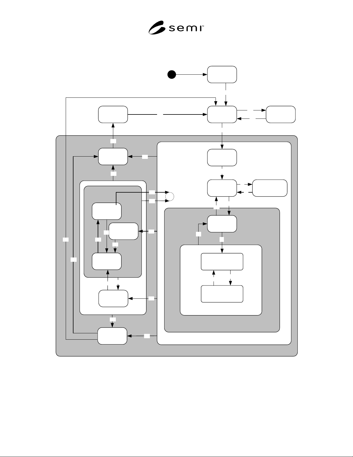
SEMI E123-0703 © SEMI 2003 3
the HSEM-defined state transitions. All expected transitions between HSEM states must occur.
6.3 HSEM State Model
3
EXECUTING
PROCESS
PROCESS ACTIVE
STOPPING
SETTING
UP
READY
LOADING
AWAITING
COMMAND
CONTACTOR
OPEN
IDLE
INIT
IDLE with
ALARM
ABORTED
WORKING
ABORTING
PAUSING
PAUSED
ALARM
PAUSED
CHECKING
PAUSE
PROCESS
PAUSE
2
19
1
7
PRELOADING
5
C
6
9
4
8
18
17
15
14
12
13
20
16
21
22
23
24
25
26
27
28
29
30
11
10
Figure 1
HSEM Processing State Model