semi合集-English.pdf - 第4762页
SEMI C14-95 © SEMI 1995, 2002 2 system. C are should be taken t o provide an ade quate exhaust lengt h so that back diffusi on of particles does not affect the system b ackground at 2 times the sampling flow rate. This l…

SEMI C14-95 © SEMI 1995, 2002 1
SEMI C14-95 (Reapproved 1102)
TEST METHOD FOR PARTICLE SHEDDING PERFORMANCE OF 25 cm
GAS FILTER CARTRIDGES
This test method was technically approved by the Global Gases Committee and is the direct responsibility of
the North American Gases Committee. Current edition approved by the North American Regional Standards
Committee on August 29, 2002. Initially available at www.semi.org September 2002; to be published
November 2002. Originally published in 1995; previously published in 1996.
1 Purpose
1.1 The purpose of this document is to define a
comprehensive standard test sequence to derive
particle-related qualification data for 25 cm (10 inch)
filter cartridges.
2 Scope
2.1 This test method defines a particle shedding
evaluation method for 25 cm filter cartridges of various
media (e.g., PTFE, PVDF, polycarbonate, nylon, and
polysulfone) commonly used individually or in
assemblies to remove particles from gas lines. The filter
cartridges are separable from the housings which can be
cleaned and tested independently.
2.2 This standard does not purport to address safety
issues, if any, associated with its use. It is the
responsibility of the users of this standard to establish
appropriate safety health practices and determine the
applicability or regulatory limitations prior to use.
3 Limitations
3.1 These test methods do not apply to point-of-use
(POU) filters, for which separate methods have been
developed.
3.2 Cartridge filter performance cannot be
characterized by a single data point, as conditions of
use (e.g., pressure drop, transient pressure surges)
determine the importance of a particular measurement.
A sequence of tests, designed to measure filter
responses under various conditions, is necessary when
evaluating cartridge filters.
3.3 The order of the test sequence will affect the test
results, and it is designed for fair comparisons of
different aspects of filter operations. Hence, it is
important to follow the prescribed test sequence.
4 Summary of Method
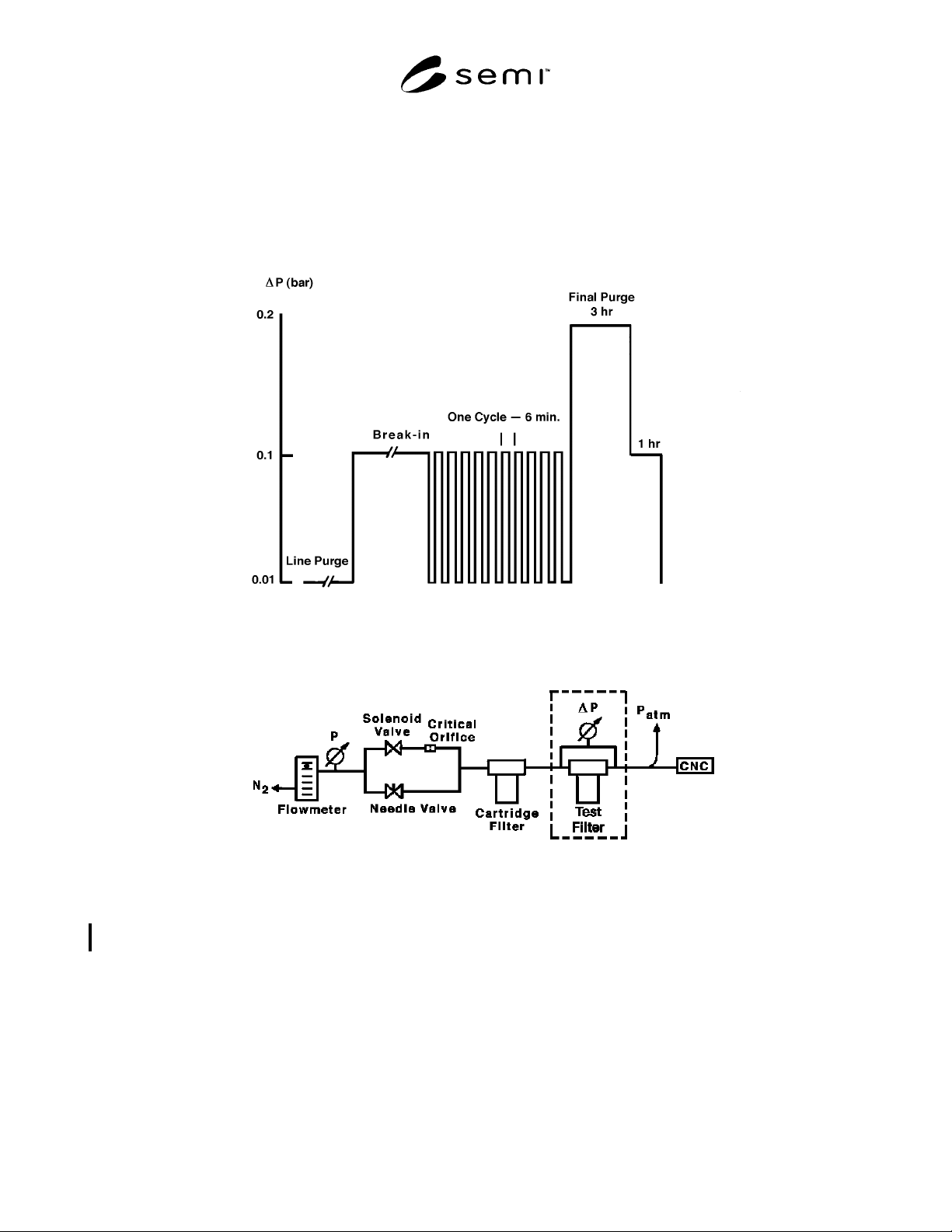
4.1 The test sequence (shown schematically in Figure
1) consists of three steps:
1. Break-in
2. Pulse
3. Final Purge
5 Apparatus and Facility
5.1 Gas Source — Clean, dry nitrogen or dry air with
less than 0.5 ppm moisture and less than 0.5 ppm total
hydrocarbons.
5.2 Particle Detectors — A condensation nucleus
counter (CNC) with a counting efficiency of 50%, as
reported by the manufacturer, at 0.01 µm is
recommended to measure total particle concentration
greater than 0.01 µm.
5.3 Test Environments — A clean room environment is
not required during testing; however, the test
component should be unpacked and assembled in a
Class 100 clean area to prevent ambient contamination.
5.4 Configuration for Break-in Test — The schematic
of the test setup apparatus is shown in Figure 2. All
components used in the test apparatus, including the
flowmeter, valves, tubing, and filter housing, are 2.5 cm
(1 inch) components or have 2.5 cm (1 inch) inlet and
outlet connections. The apparatus consists of (1) a
differential pressure sensor that can accurately measure
∆p in the range 0.01 bar (0.15 psid) to 0.2 bar (3.0 psid)
between the upstream and downstream pressure of the
test component, (2) a flow control system that permits
instantaneous change of flow corresponding to a ∆p of
0.01 bar to 0.2 bar across the filter, and (3) a CNC
downstream of the test filter.
5.5 Configuration for Pulse Test — The schematic of
the test setup is the same as the break-in test.
5.6 Sample Installation — Reasonable precautions
should be taken when installing the test filter or spool
piece to avoid particle contamination of the system
from ambient air. These precautions may include, but
are not limited to, installation in a Class 100 laminar
flow area, installation in a purged glove bag or other
controlled ambient enclosure, use of a purge flow
downstream of the sample point so that all parts of the
system are under purge, isolation, or termination of the
CNC sample flow, and isolation of the isokinetic
sampler exhaust from ambient.
5.7 Sampling System Design — Customary practices
should be employed for the design of the sampling

SEMI C14-95 © SEMI 1995, 2002 2
system. Care should be taken to provide an adequate
exhaust length so that back diffusion of particles does
not affect the system background at 2 times the
sampling flow rate. This length will depend upon the
particle concentration in the ambient environment and
other factors.
6 Procedure
6.1 Static Background Test
6.1.1 This test applies to all apparatus described in this
document and should be performed prior to other tests.
6.1.2 Remove the filter cartridge from the filter
housing and replace the test filter in Figure 2 with the
empty housing.
6.1.3 Purge the system at 100 m
3
/hr (3530 standard
cubic feet per hour (scfh)). Measure particle
concentration for a minimum of 45 sample intervals,
each at least 6 standard liters (0.19 scf) or 4 minutes,
whichever is greater. Continue to purge the system until
45 consecutive sample intervals without a particle being
detected are recorded.
6.2 Dynamic Background Test
6.2.1 This test applies to the apparatus for pulse test as
shown in Figure 2 with the test filter replaced by an
empty filter housing.
6.2.2 Purge at a flow rate of 5 m
3
/hr (177 scfh) until 5
consecutive 60-second sample intervals without a
particle being detected are recorded.
6.2.3 Set the CNC sample interval time to 180 seconds.
Synchronize the start of this test with the start of a CNC
sample interval.
6.2.4 Purge at a flow rate of 5 m
3
/hr (177 scfh) for 190
seconds.
6.2.5 Instantaneously switch to a flow rate of 100 m
3
/hr
(3530 scfh) by turning ON the solenoid valve and purge
for 160 seconds.
6.2.6 Turn OFF the solenoid valve and purge at a flow
rate of 5 m
3
/hr (177 scfh) for 200 seconds.
6.2.7 Repeat Section 6.2.5 and Section 6.2.6 until 20
consecutive pulses without a particle being detected are
recorded.
6.3 Break-in Test
6.3.1 The test setup apparatus is shown in Figure 2.
Purge at a relatively low flow rate corresponding to a
∆p of 0.01 bar (0.15 psid) across the filter until 5
consecutive 60-second sample intervals without a
particle being detected are recorded.
6.3.2 Increase the purge flow rate so that the
corresponding ∆p is at least 0.1 bar and the flow rate is
at least 45 m
3
/hr (1590 scfh).
6.3.3 Record hourly particle concentration averages.
6.3.4 Stop the test when no particles are detected in 3
consecutive hourly sampling intervals.
6.4 Pulse Test
6.4.1 The apparatus is shown in Figure 2. Purge at a
relatively low flow rate corresponding to a ∆p of 0.01
bar across the filter until 5 consecutive 60-second
sample intervals without a particle being detected are
recorded.
6.4.2 Set the CNC sample interval to 180 seconds.
Synchronize the start of this test with the start of a CNC
sample interval.
6.4.3 Purge at a low flow rate corresponding to a ∆p of
0.01 bar across the filer for 190 seconds.
6.4.4 Instantaneously switch to a higher flow rate
corresponding to a ∆p of 0.1 bar (0.15 psid) across the
filter by turning ON the solenoid valve and purge for
160 seconds.
6.4.5 Turn OFF the solenoid valve and purge at a low
flow rate (∆p = 0.01 bar) of 200 seconds.
6.4.6 Repeat Section 6.4.4 and Section 6.4.5 (160 secs
ON and 200 secs OFF) for a series of 10 flow pulses.
6.5 Final Purge Test
6.5.1 Purge the filter at a ∆p of 0.2 bar (3 psid) or a
flow rate of 90 m
3
/hr (3180 scfh), whichever is greater,
for 3 hours. Record the particle concentration.
6.5.2 Decrease the flow so that ∆p = 0.1 bar (0.15 psid)
or the flow rate is 45 m
3
/hr (1590 scfh), whichever is
greater, and purge for 1 hour. Record the particle
concentration.
7 Reporting of Test Results
7.1 Raw data should be reported for each test in the
format of a table including the number of sample
intervals, the sampling volume of each interval, the
sampling time of each interval, and the total number of
particles registered in each interval. In addition, the
relevant parameters for each test described in Sections
7.2–7.6 should be identified.
7.2 Static Background Test — Identify the period of
time required to obtain 3 consecutive hourly sampling
intervals without a particle being detected.
7.3 Dynamic Background Test — Identify period of
time required to obtain 20 consecutive flow pulses
without a particle being detected.
SEMI C14-95 © SEMI 1995, 2002 3
7.4 Break-in Test — Identify the period of time required to obtain 3 consecutive one hour sampling intervals
without detection of particles and the total number of particles recorded during this period.
7.5 Pulse Test — Identify the number of pulses during which particles were detected and the total number of
particle counts.
7.6 Final Purge Test — Identify the average particle concentration at each pressure.
Figure 1
Schematic of a Standard Test Sequence for Evaluating 10-inch Filters
Figure 2
Schematic of the Line Purge Test Setup
NOTICE: SEMI makes no warranties or representations as to the suitability of the standards set forth herein for
any particular application. The determination of the suitability of the standard is solely the responsibility of the user.
Users are cautioned to refer to manufacturer’s instructions, product labels, product data sheets, and other relevant
literature respecting any materials mentioned herein. These standards are subject to change without notice.
The user’s attention is called to the possibility that compliance with this standard may require use of copyrighted
material or of an invention covered by patent rights. By publication of this standard, SEMI takes no position
respecting the validity of any patent rights or copyrights asserted in connection with any item mentioned in this
standard. Users of this standard are expressly advised that determination of any such patent rights or copyrights, and
the risk of infringement of such rights, are entirely their own responsibility.
Copyright by SEMI® (Semiconductor Equipment and Materials
International), 3081 Zanker Road, San Jose, CA 95134. Reproduction o
f
the contents in whole or in part is forbidden without express written
consent of SEMI.