semi合集-English.pdf - 第415页
SEMI E56-1104 © SEMI 1996, 2004 4 be from beyon d the deadband. Short - term reproducibility includes repeatab ility, hysteresis, deadband, a nd short-te rm drift . 5.2.28 setpoint — the input signal provided to achieve …
SEMI E56-1104 © SEMI 1996, 2004 3
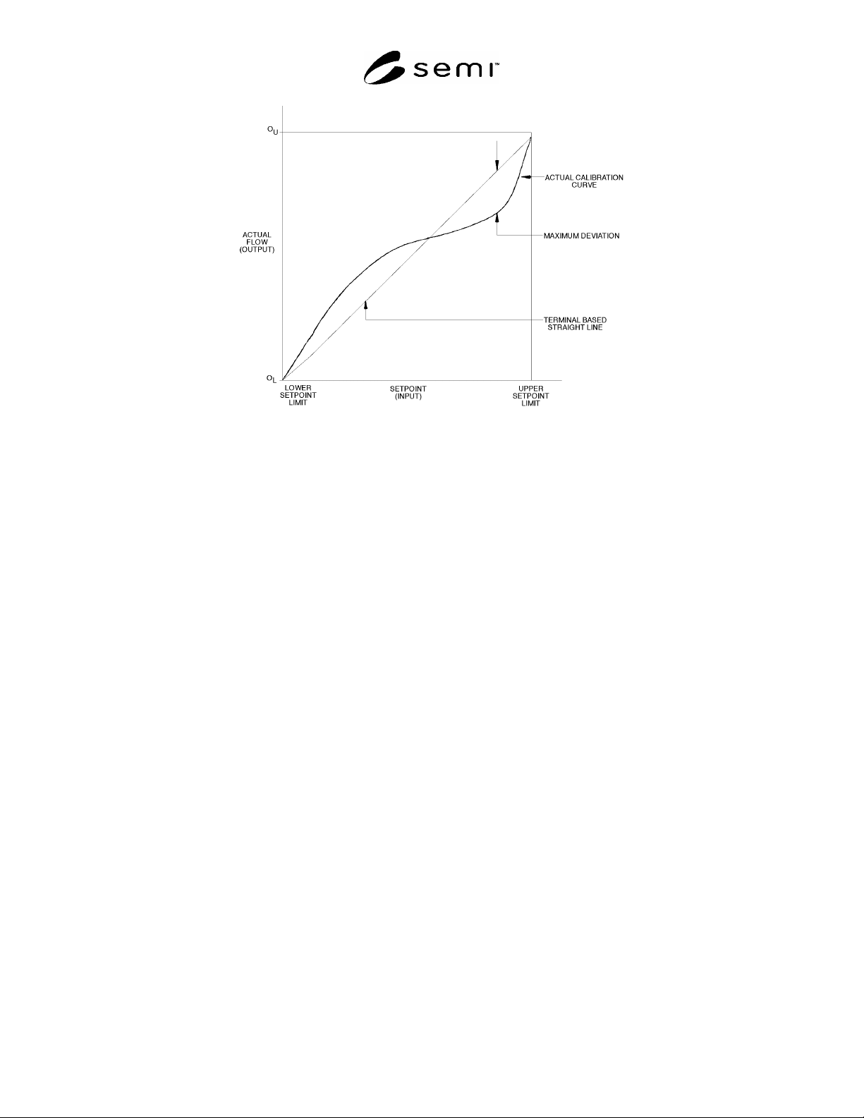
Figure 1
Terminal-Based Linearity for Mass Flow Controller
5.2.14 hysteresis — that property of an element
evidenced by the dependence of the value of the output,
for a given excursion of the input, upon the history of
the prior excursions and the direction of the current
traverse.
5.2.15 indicated flow — flow indicated by MFC under
test. Electrical output of the DUT.
5.2.16 linearity — the closeness to which a curve
approximates a straight line.
5.2.17 linearity, terminal-based — the maximum
absolute value of the deviation of the accuracy curve
(average of upscale and downscale values) from a
straight line through the upper and lower setpoint limits
of the accuracy curve (see Figure 1).
5.2.18 measured value — the actual flow through a
device under test, expressed in sccm or slm, as
measured by a standard, preferably primary.
5.2.19 measured value, average — the sum of all
readings (both upscale and downscale) for all cycles, at
a single setpoint, divided by the number of these
readings.
5.2.20 operating conditions, normal — the range of
operating conditions within which a device is designed
to operate and for which operating influences are stated
[ISA S51.1].
5.2.21 operating conditions, reference — the range of
operating conditions of a device within which operating
influences are negligible [ISA S51.1].
5.2.22 operating influence — the change in a
performance characteristic caused by a change in a
specified operating condition from reference operating
conditions, all other conditions being held within the
limits of reference operating conditions [ISA S51.1].
5.2.23 pneumatic noise — localized, random variations
in pressure and flow.
5.2.24 precision — the closeness of agreement among
the measured values at a setpoint. It is often expressed
as a standard deviation.
5.2.25 repeatability — the closeness of agreement
among a number of measured values at a setpoint,
under the same operating conditions, operator,
apparatus, laboratory, and short intervals of time. It is
usually measured as a nonrepeatability and expressed as
a repeatability in percent of reading.
5.2.26 reproducibility — the closeness of agreement
among repeated measured values at a setpoint, within
the specified reference operating conditions, made over
a specified period of time, approached from both
directions. Reproducibility includes hysteresis,
deadband, long-term drift, and short-term
reproducibility.
NOTE 1: Between repeated measurements, the input may
vary over the range, and operating conditions may vary within
normal operating conditions.
5.2.27 reproducibility, short-term — the closeness of
agreement among a number of measured values at a
setpoint, under the same operating conditions, operator,
apparatus, laboratory and short intervals of time,
approached from both directions. The approach must
SEMI E56-1104 © SEMI 1996, 2004 4
be from beyond the deadband. Short-term
reproducibility includes repeatability, hysteresis,
deadband, and short-term drift.
5.2.28 setpoint — the input signal provided to achieve
a desired flow, reported as sccm, slm, or percent-full
scale.
5.2.29 setpoint limit, lower — the lowest setpoint at
which the instrument is specified to operate.
5.2.30 setpoint limit, upper — the highest setpoint at
which the instrument is specified to operate, usually full
scale.
5.2.31 settling time — the time between the set point
step change and when the actual flow remains within
the specified band (see SEMI E17).
5.2.32 span — the full-scale range of the DUT.
5.2.33 stability — the ability of a condition to exhibit
only natural, random variation in the absence of
unnatural, assignable-cause variation.
5.2.34 standard conditions — 101.32 kPa, 0.0°C (14.7
psia, 32°F)
5.2.35 uncertainty, total — the range within which the
true value of the measured quantity can be expected to
fit; an indication of the variability associated with a
measured value that takes into account the two major
components of error, bias and the random error
attributed to the imprecision of the measurement
process.
5.2.36 upscale reading — a reading approached from a
setpoint less than the current setpoint and beyond the
deadband.
5.2.37 upscale value, average — the sum of all upscale
readings, in one cycle, at a single setpoint, divided by
the number of these values.
5.2.38 zero drift — the undesired change in electrical
output, at a no-flow condition, over a specified time
period, reported in sccm or slm.
5.2.39 zero offset — the deviation from zero, at a no-
flow condition, reported in sccm or slm.
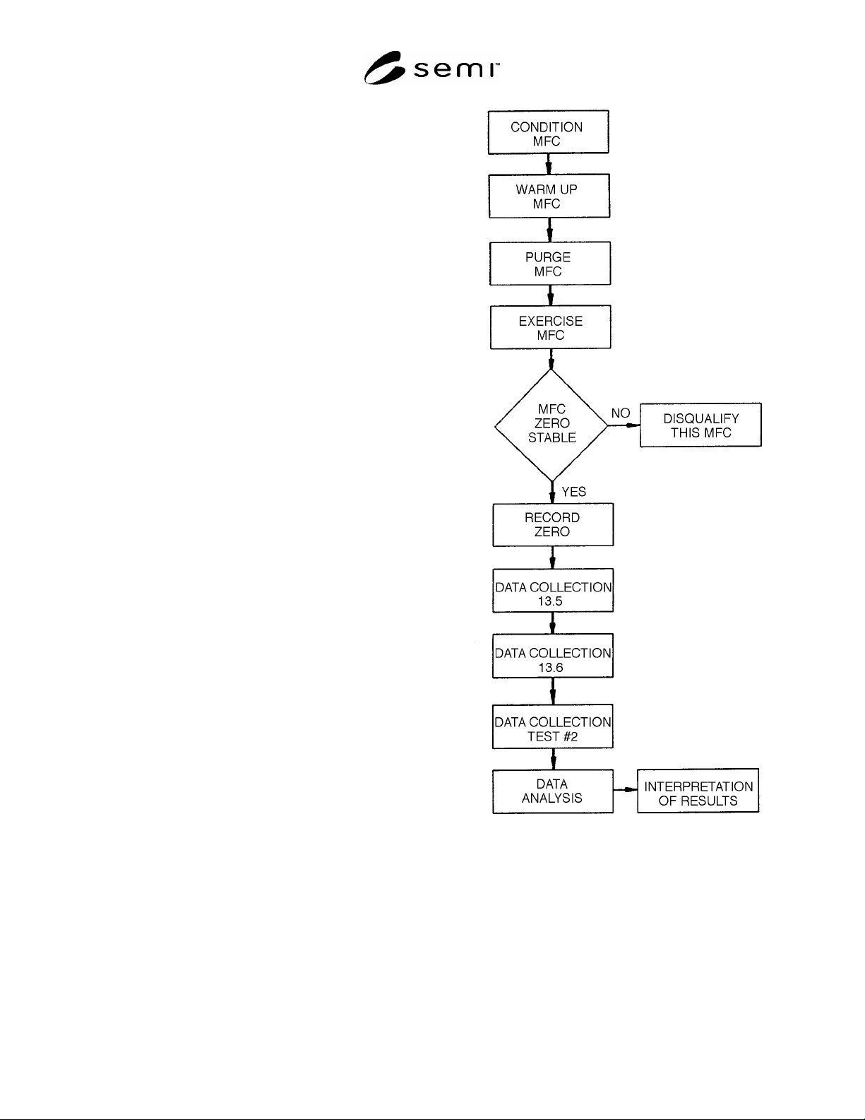
6 Summary of Test Method
6.1 Specific procedures are given for characterizing
MFCs discharging to atmospheric pressure or into a
vacuum using accepted reference standards to
determine accuracy, linearity, repeatability, short-term
reproducibility, hysteresis, and deadband (see Figure 2).
Figure 2
Test Flowchart
7 Interferences
7.1 The accuracy rating of the measuring equipment
must include superior measurement capability
compared with that of the DUT. In no instance should
the accuracy rating of the measuring equipment be less
than twice that of the DUT (e.g., if the accuracy of the
DUT is ± 1 sccm, then the accuracy of the measuring

SEMI E56-1104 © SEMI 1996, 2004 5
device must be better than or equal to ± 1/2 sccm). The
traceability of all the pertinent measuring instruments
and devices should be realistically established and
quantified.
7.1.1 In addition, take care when using test instruments
with a specified accuracy expressed in percent of full
scale. For example, if an instrument with a specified
accuracy of ± 0.1% of full scale is used to measure the
output of the DUT, but this output signal falls only
within the lower third of the scale of the instrument, the
effective accuracy over the range of the instrument
being used may be ± 0.3%, which is unsuitable for
many applications.
7.2 Use special precautions to ensure that minimum
effects result from pneumatic noise in flow lines.
Monitor pressure both upstream and downstream of the
MFC to ensure that pneumatic noise is minimized.
7.3 The DUT should be installed so that the inlet flow
can be fully developed, pulsation-free, for the specific
conditions. This can be achieved by plumbing a
straight length of tubing 40–50 diameters long upstream
and another straight length 5 diameters long
downstream of the DUT. (For additional information
about inlet effects, refer to ASME MFC-10M.)
7.4 At regular calibration intervals, verify electrical
signals directly at the MFC connector to ensure that
there are no unacceptable line losses in the cables.
8 Apparatus
8.1 heat exchanger
8.2 flow standard
8.3 pressure transducer
8.4 back pressure regulator
8.5 temperature probe
8.6 digital voltmeter
8.7 setpoint generator
8.8 power supply
9 Technical Precautions
9.1 Many analog-to-digital converter cards do not
differentiate between measurements of less than zero
and zero. It may be necessary to use a digital voltmeter
to record measurements below zero volts. Some MFCs
do not differentiate between measurements of less than
zero and zero. This may bias the results.
9.2 The manufacturer’s specifications and instructions
for installation and operation must be applied during all
testing.
9.3 All electrical measurements should be read on
devices with at least 4.5 digits of resolution. These
devices must have valid calibration certifications.
9.4 The mounting position of the device must be in
accordance with the manufacturer's specifications. No
external mechanical constraints beyond the
manufacturer’s recommended mounting position shall
be permitted.
10 Preparation of Apparatus
10.1 Figure 3 is a representation of a recommended
generic testing apparatus. The flow standard is shown
downstream of the device under test (DUT). It may be
placed upstream of the DUT if the flow standard cannot
be exposed to a low pressure environment. In this case,
the user should be aware of possible back pressure
effects on the flow standard.
10.2 The flow standard can be of any type, including
laminar flow elements, volumetric standards, rate of
rise, or mass flow meters.