semi合集-English.pdf - 第7717页
SEMI T11-0703 © SEMI 2002, 2003 2 5.3.3 quiet z one — an unpatterned, unm arked area that surrounds a mark field. 6 Ordering Information 6.1 Purchase orders for su bstrates furnished to thi s specification shall specify …
SEMI T11-0703 © SEMI 2002, 2003 1
SEMI T11-0703
SPECIFICATION FOR MARKING OF HARD SURFACE RETICLE
SUBSTRATES
This specification was technically approved by the Global Traceability Committee and is the direct
responsibility of the North American Traceability Committee. Current edition approved by the North
American Regional Standards Committee on April 11, 2003. Initially available at www.semi.org June 2003;
to be published July 2003. Orignally published November 2002.
1 Purpose
1.1 This specification provides a symbology for
marking hard surface reticle substrates within the edge
exclusion area of the substrate.
2 Scope
2.1 This specification defines the geometric and spatial
relationships and content (including error checking and
correcting code) of square two-dimensional, machine-
readable, Data Matrix symbols for pattern-surface
marking of resist-coated 6 inch reticle substrates that
comply with the specifications of SEMI P1.
2.1.1 This specification addresses only the Data Matrix
field characteristics and location. This Data Matrix
field may contain the information previously contained
in various bar code symbols on 6 inch reticles. The
format of such information is not detailed in this
specification.
NOTICE: This standard does not purport to address
safety issues, if any, associated with its use. It is the
responsibility of the users of this standard to establish
appropriate safety and health practices and determine
the applicability of regulatory or other limitations prior
to use.
3 Limitations
3.1 This specification does not cover any other code
fields on the reticle. These might be stepper-specific or
user-specific or both. The location, symbology and
content of these other fields, if they exist, are
determined between reticle supplier and user.
NOTE 1: Data Matrix symbology is applicable to a broad
range of semiconductor products including virgin wafers,
processed and patterned FPD substrates, lead frames and
reticles. The format and algorithms of this code are based on
two-dimensional symbology specified in ISO/IEC 16022 —
International Symbology Specification – Data Matrix.
3.2 Although this specification does not specify the
marking techniques to be employed when complying
with its requirements, it is assumed that the symbol will
be obtained by exposure of individual dots in a resist
coating with an e-beam, laser or other pattern-
generation tool.
NOTE 2: An experiment executed by International Sematech
found such e-beam marks to be suitable for the application.
4 Referenced Standards
4.1 SEMI Standard
SEMI P1 — Specification for Hard Surface Photomask
Substrates
4.2 ANSI Standard
1
ANSI MH10.8.2 — Data Application Identifier
Standard
4.3 ISO/IEC Standard
2
ISO/IEC 16022 — International Symbology
Specification – Data Matrix
4.4 Uniform Code Council Standard
3
Manufacturer Identification Codes
NOTICE: As listed or revised, all documents cited
shall be the latest publications of adopted standards.
5 Terminology
5.1 Terms relating to the data matrix code symbol
characteristics are defined in ISO/IEC 16022.
5.2 Definitions of terms relating to the marking area
are as follows:
5.3 Definitions
5.3.1 mark area — a rectangular area containing the
mark field(s) and the surrounding quiet zone.
5.3.2 mark field — an area within which all mark
elements occur.
1 American National Standards Institute, New York Office: 11 West
42nd Street, New York, NY 10036, USA. Telephone: 212.642.4900;
Fax: 212.398.0023 Website: www.ansi.org
2 International Organization for Standardization, ISO Central
Secretariat, 1, rue de Varembe, Case postale 56, CH-1211 Genava 20,
Switzerland. Telephone: 41.222.749.01.11; Fax: 41.22.733.34.30
Website: www.iso.ch
3 Uniform Code Council, 8163 Old Yankee Road, Dayton, Ohio
45458 Website: www.uc-council.org
SEMI T11-0703 © SEMI 2002, 2003 2
5.3.3 quiet zone — an unpatterned, unmarked area that
surrounds a mark field.
6 Ordering Information
6.1 Purchase orders for substrates furnished to this
specification shall specify the following optional items:
6.1.1 Number (15 to 91) of message characters.
6.1.2 Content of Message Characters 16 and up, if
present.
7 Requirements
7.1 Data Matrix Code Symbol Dimensions
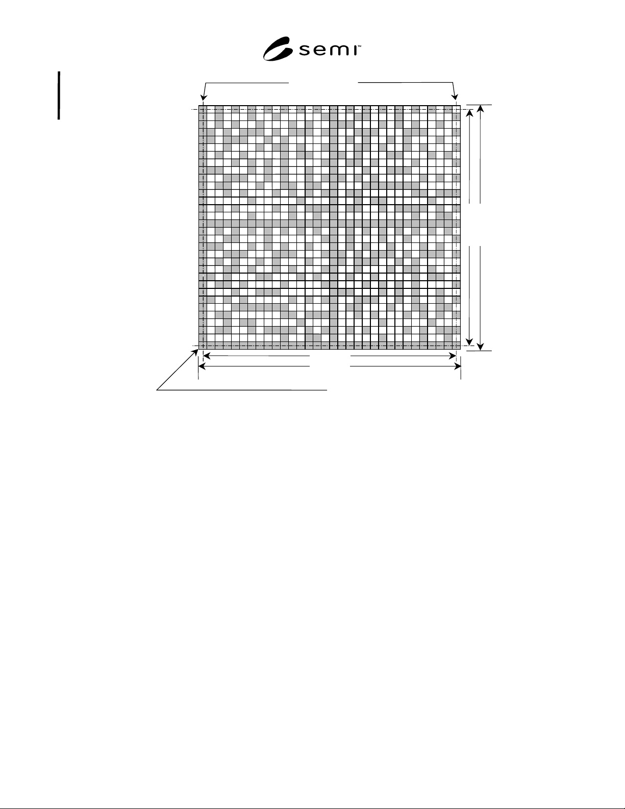
7.1.1 Each square matrix code symbol shall be
composed of an array of 32 rows and 32 columns (see
Table 1 and Figure 1) as defined in compliance with
ISO/IEC 16022.
7.2 Cell Dimensions
7.2.1 Cell spacing shall be 100 µ m, center to center.
7.2.2 Cell shape shall be square.
7.2.3 Cell size shall be 100 ± 5 µ m.
7.2.4 Dot Misalignment — The symbol shall be
readable in accordance with ISO/IEC 16022.
7.3 Border Rows and Columns (see Figure 1)
7.3.1 One border row and one border column shall
contain a dot in each cell. These are identified as the
primary border row and the primary border column.
These are used by the code reader to determine the
orientation of the matrix.
7.3.1.1 The opposing (secondary) border row and
column shall contain dots in alternating cells, as shown
in Figure 1.
7.3.2 For square Data Matrix code symbols, the
reference point of the symbol is generally the physical
centerpoint of the cell common to the primary border
row and the primary border column. However, for the
present application it is more convenient to reference
the location of the Data Matrix code symbol to the
bottom left corner of the cell containing the reference
point, identified in the figures as the “reference corner.”
7.4 Quiet Zone
7.4.1 The quiet zone surrounding the Data Matrix code
symbol shall be four cells (400 µm) wide.
7.4.2 The area between the quiet zone and the nearest
side of the pellicle frame shall be filled with an
unpatterned chrome film.
7.5 Content of the Data Matrix Code Symbol
7.5.1 Each square Data Matrix code symbol shall
contain between 15 and 91 message characters, together
with error checking and correcting (ECC) 200 code
characters, encoded in accordance with ISO/IEC 16022.
7.5.2 The message characters may include any of those
designated as EDIFACT in Table 5 and Annexe J.3 of
ISO/IEC 16022.
7.5.3 The first 15 message characters shall contain
supplier-assigned 8-character substrate identification
code, followed by a 7-character supplier (manufacturer)
identification code defined by UCC as a six-digit
company identification, preceded by a zero (0).
7.5.4 The remaining message characters, if any, shall
contain information as agreed between the supplier and
user. This may require field identifiers and field
concatenators (see ANSI MH10.8.2).
7.6 Location of the Data Matrix Code Symbol
7.6.1 With the substrate positioned front surface up and
with the substrate’s reference corner toward the
operator and to the operator’s left, the lower left corner
of the Data Matrix code symbol shall be located
139.6 ± 0.5 mm to the right and 110.4 ± 0.5 mm above
the substrate’s reference corner.
7.6.2 This places the 32 row × 32 column square Data
Matrix code symbol entirely within a 14 mm wide edge
exclusion area (see Figure 2).
7.6.3 The primary border row of the symbol shall be
parallel with the adjacent edge of the substrate ± 10.0° .
The primary border column of the symbol shall be
nominally perpendicular to the same edge.
7.6.4 Mark Area Dimensions — The mark area shall be
4.0 mm × 4.0 mm.
Table 1 Data Matrix Code Symbol Dimensions
Type of array Square
Cell spacing (center to center)
100 µm (nominal)
Dot size (diameter or edge
length)
100 ± 5 µm
Dot misalignment
10 µm, max.
Number of cells in row 32
Number of cells in column 32
C
1
3.100 mm
R
1
3.100 mm
C
2
3.200 mm
R
2
3.200 mm
Width of quiet zone
400 µm (nominal)
SEMI T11-0703 © SEMI 2002, 2003 3
Data Matrix Code Symbol Reference Corner
C
2
C
1
R
1
R
2
Secondary Border Ro
w
Secondary Border Column
Primary Border Row
Primary Border Column
NOTE: All dimensions in millimeters.
Figure 1
Data Matrix Code Symbol Showing Border Rows and Columns