semi合集-English.pdf - 第540页
SEMI E77-1104 © SEMI 1998, 2004 8 14.2 Conversion F actors — The conversion factor bet ween any Gas A an d any Gas B at ea ch setpoint i s calculat ed as follows: conversion f acto r ( Gas A / Gas B ) @ X % s etpoint = a…
SEMI E77-1104 © SEMI 1998, 2004 7
Table 2 Statistical Performance
MFC Mfg/Model/Serial # ____________________________________
Name Plate Gas/Range ____________________________________
Test Gas ____________________________________
Temp ___________ Bar ___________ Date ___________
Factory Calibration Gas ____________________________________
Column A
D.U.T. Setpoint
(% F.S.)
Column B
Mean Corrected Standard
Flow Reading (SCCM)
Column C
Standard Deviation
Flow (SCCM)
10
20
30
40
50
60
70
80
90
100
Nameplate Gas/Range ___________ Test Gas ________________ Date _____________
MFG/Serial # _________________ Barometric Pressure _______________
Inlet Pressure _________________ Temperature _____________________
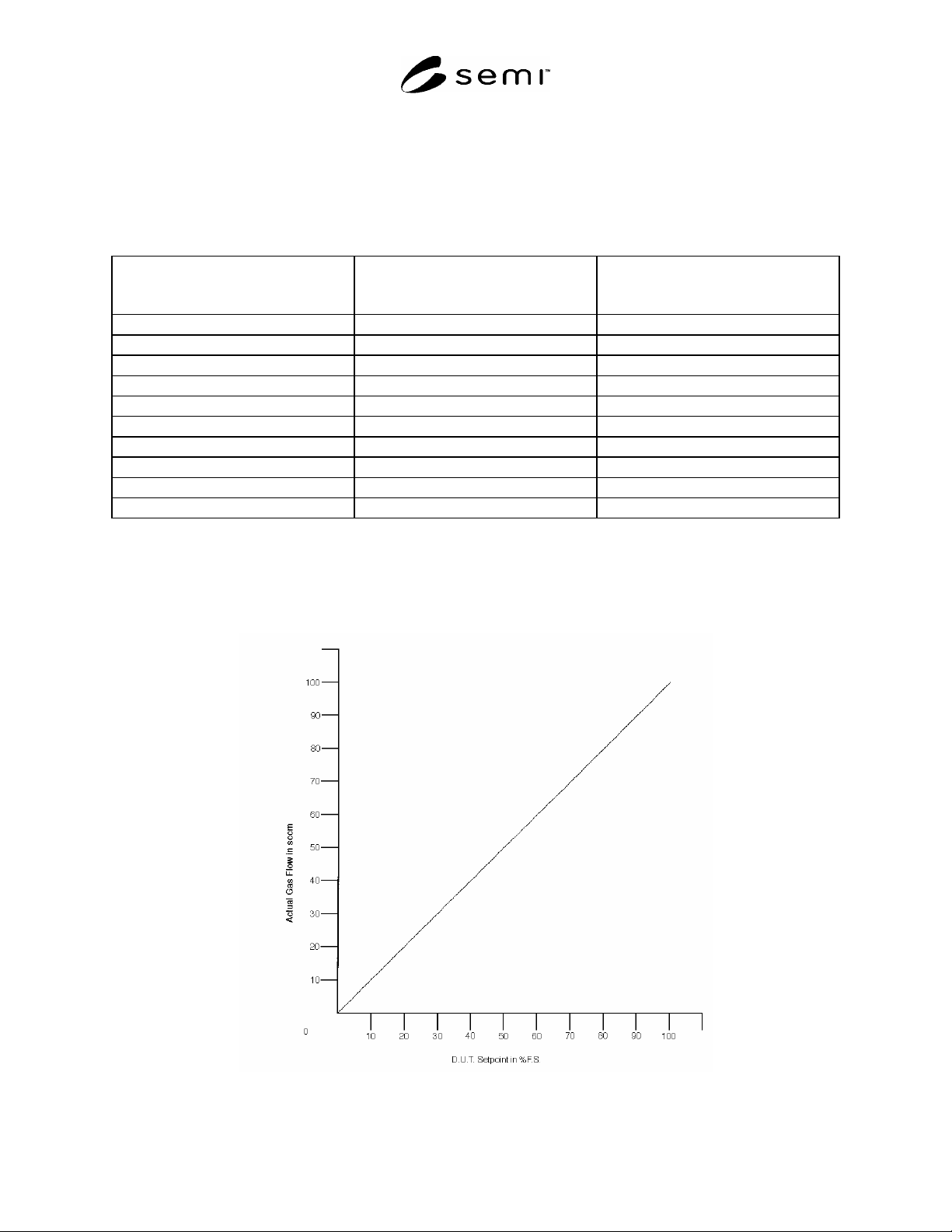
Figure 2
D.U.T. Setpoint vs. Gas Flow

SEMI E77-1104 © SEMI 1998, 2004 8
14.2 Conversion Factors — The conversion factor between any Gas A and any Gas B at each setpoint is calculated
as follows:
conversion
f
acto
r
(Gas
A
/ Gas B) @
X
%
s
etpoint =
average actual flow @ X% setpoint on Gas A
average actual flow @ X% setpoint on Gas B
where X = setpoint value
14.3 Calculate the conversion factors for the gas tested and record in Table 3.
Table 3 MFC Conversion Factors for Each Setpoint
MFC Mfg/Model/Serial # ____________________________________
Name Plate Gas/Range ____________________________________
Test Gas ____________________________________
Temp ___________ Bar ___________ Date ___________
Factory Calibration Gas ____________________________________
Column A
D.U.T. Setpoint
(% F.S.)
Column B
CF (Gas A / Gas B)
100%
90
80
70
60
50
40
30
20
10
SEMI E77-1104 © SEMI 1998, 2004 9
14.4 Interpretation
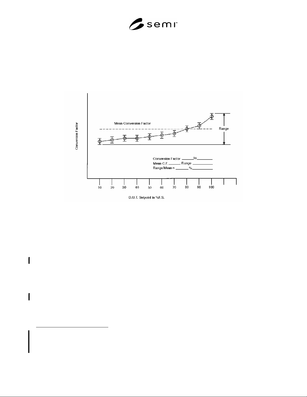
14.4.1 Figure 3 illustrates the conversion factor between two specific gases as a function of setpoint. It may be used
to accurately map from one gas to the other and may predict the flow error that will result if the average conversion
factor is used.
Nameplate Gas/Range ___________ Test Gas ________________ Date _____________
MFG/Serial # _________________ Barometric Pressure _______________
Inlet Pressure _________________ Temperature _____________________
Figure 3
Conversion Factors vs. D.U.T. Setpoint
15 Reporting Results
15.1 MFC Conversion Factors
15.1.1 Plot the conversion factor from Gas A to Gas B against the D.U.T. setpoint. Note the mean value and range
of values (see Figure 3).
16 Related Documents
16.1 ANSI Standards
1
ANSI C39.5 — Safety Requirements for Electrical and Electronic Measuring and Controlling Instrumentation
ANSI C42.100 — Dictionary of Electrical and Electronics Terms
ANSI MC4.1 — Dynamic Response Testing of Process Control Instrumentation
16.2 IEC Standard
2
IEC 546 — Methods of Evaluating the Performance of Controllers with Analogue Signals for Use in Industrial
Process Control
1 American National Standards Institute, Headquarters: 1819 L Street, NW, Washington, DC 20036, USA. Telephone: 202.293.8020; Fax:
202.293.9287, New York Office: 11 West 42nd Street, New York, NY 10036, USA. Telephone: 212.642.4900; Fax: 212.398.0023, Website:
www.ansi.org
2 International Electrotechnical Commission, 3, rue de Varembé, Case Postale 131, CH-1211 Geneva 20, Switzerland. Telephone:
41.22.919.02.11; Fax: 41.22.919.03.00, Website: www.iec.ch