semi合集-English.pdf - 第6346页
3 SEMI G69-0996 © SEMI 1996, 2004 Figure 2 Sample for Pull Method Adhesive Area Molding Compound Sample Thickness 16 ± 0.8 mm 2 (both sides) 3.5–4.0 mm (equivalent to DIP 16 300 mil)
SEMI G69-0996 © SEMI 1996, 2004 2
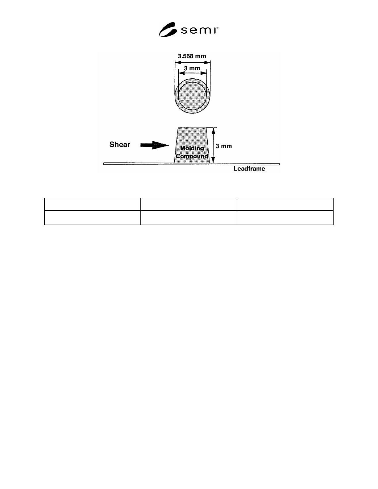
Figure 1
Sample for Shear Method
Adhesive Area Leadframe Thickness Height of Molding Compound
10 ± 0.5 mm
2
0.254–0.125 mm
(0.15 mm is recommended)
3 ± 0.15 mm
3 SEMI G69-0996 © SEMI 1996, 2004
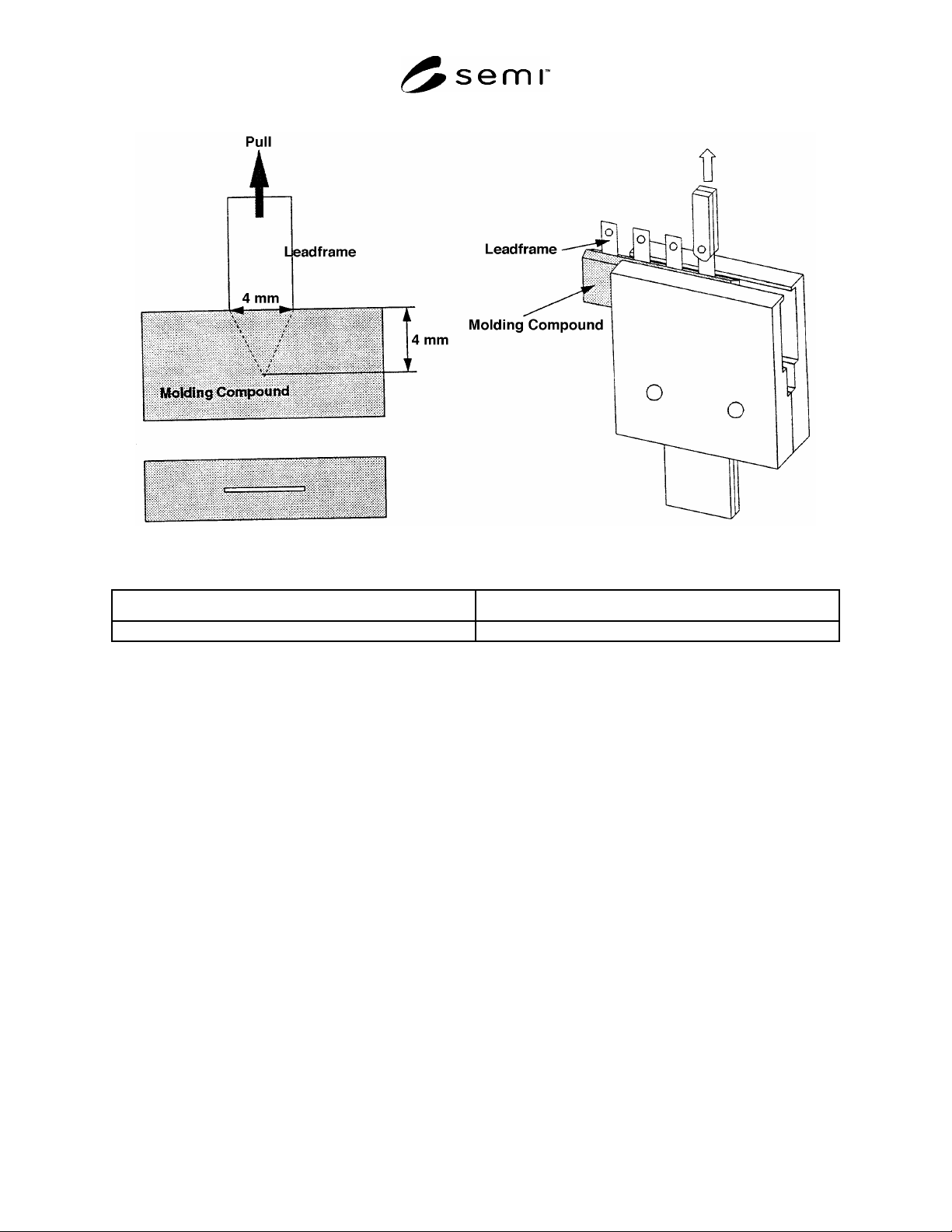
Figure 2
Sample for Pull Method
Adhesive Area Molding Compound Sample Thickness
16 ± 0.8 mm
2
(both sides) 3.5–4.0 mm (equivalent to DIP 16 300 mil)
SEMI G69-0996 © SEMI 1996, 2004 4
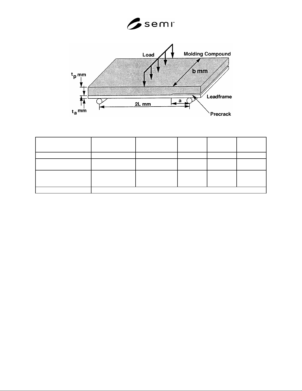
Figure 3
Sample for Three-Point Bending Method
Molding Compound
Thickness t
p
(mm)
Leadframe Thickness
t
a
(mm)
Span 2L (mm)
Pre-Crack
Length a (mm)
Sample Width
b (mm)
Standard 1.5 0.25 45 10–15 6
Type A
(for low adhesive strength)
0.8 0.2 35 8–10 4
Type B
(for high temperature
measurement)
4 0.5 50 10–15 6
Other Sample Types The following equations should be satisfied 2L 8 (t
p
+ t
a
) and L - a 2 (t
p
+ t
a
)
7 Sampling Plan
7.1 The sampling plan shall be in agreement between customer and vendor. It is recommended that the following
minimum sample sizes are used:
Shear Method — Four (4) samples
Pull Method — Four (4) samples
Three-Point Bending Method — Three (3) samples in each direction
NOTE 1: Three-point bending method needs at least 2 samples to obtain adhesive strength.
8 Materials
8.1 Leadframe or appropriated sample from strip meeting dimensions for test.
8.2 Molding compound
9 Sample Preparation
9.1 Leadframe Sample Preparation
9.1.1 Process the leadframe samples through the various cleaning and heat cycles that would be normal for the
leadframe under consideration as required.
NOTE 2: When this method is applied to copper leadframes, copper oxide on the surface shall be considered when results are
interpreted.
9.2 Clean and condition the molds to provide well formed samples as required.
9.3 Set the molds to the specified temperature and record the temperature.