semi合集-English.pdf - 第6948页
SEMI S8-0705 © SEMI 1995, 2005 45 Section 5: Manual Wafer Cassette Rotatio n Device Design Section Indicator Figure 5.2 Hand grip(s) shall allow for a full “power grip” similar to grabbing a rung on a ladder or ho lding …
SEMI S8-0705 © SEMI 1995, 2005 44
Section 3: Wafer Cassette Loading
Section Indicator Figure
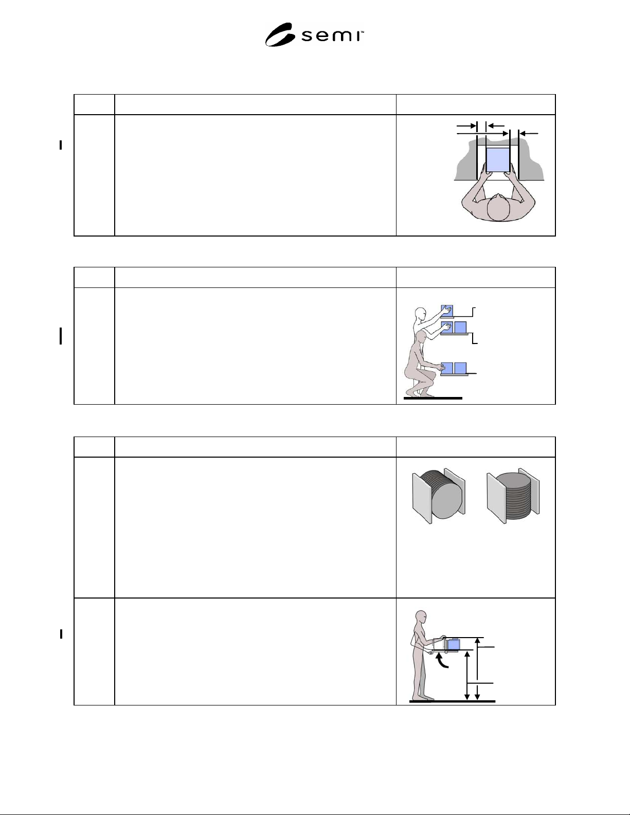
3.5 Minimum hand clearance on either side of the cassette, measured from the
side of the cassette to the nearest adjacent object.
Acceptance criterion: minimum 76 mm (3.0 in.)
NOTE: Clearance must be provided on both sides of the cassette.
Hand
clearance
Minimum
76.0 mm
(3.0 in.)
Section 4: Work in Process Storage (specific to wafer cassettes)
Section Indicator Figure
4.1 Integral wafer cassette/lot box storage shelf height (150 and 200 mm
wafer cassette/lot boxes only).
Acceptance criteria: maximum (1 box deep) 1520 mm (60 in.)
maximum (2 boxes deep) 1220 mm (48 in.)
minimum 460 mm (18 in.)
1-box deep
Maximum 1520
mm
(60 in.)
2-boxes deep
Maximum 1220
mm
(48 in.)
Minimum 460 mm
(18 in.)
Section 5: Manual Wafer Cassette Rotation Device Design
Section Indicator Figure
5.0 NOTE A: Some machines process wafers horizontally. 150–200mm
wafers are normally carried vertically, so to load these
machines, the operator must rotate the wafer cassette to
orient the wafers for processing.
NOTE B: Manual rotation of wafer cassettes can increase stress on the
machine operator’s upper extremities, which may lead to
physical strain over time and/or damage to wafers, especially
if the wafer cassettes do not have handles.
NOTE C: Manual and powered wafer cassette rotation devices are a
way to provide controlled rotation of wafer cassettes as a
means to reduce the machine operator’s physical stress and
lower the potential for wafer damage.
Manual handling
orientation for a
150-200 mm
wafer cassette
Machine handling
orientation for a
150-200 mm
wafer cassette
5.1 Handle height, couple point for hand(s) from standing surface.
Acceptance criteria: maximum 1206 mm (47.5 in.)
minimum 838 mm (33 in.)
NOTE: Coupling point is the center of a handle or the large middle
knuckle of the hand when it grasps an object.
Handle
height
Maximum
1206 mm
(47.5 in.)
Minimum
838 mm
(33 in.)
SEMI S8-0705 © SEMI 1995, 2005 45
Section 5: Manual Wafer Cassette Rotation Device Design
Section Indicator Figure
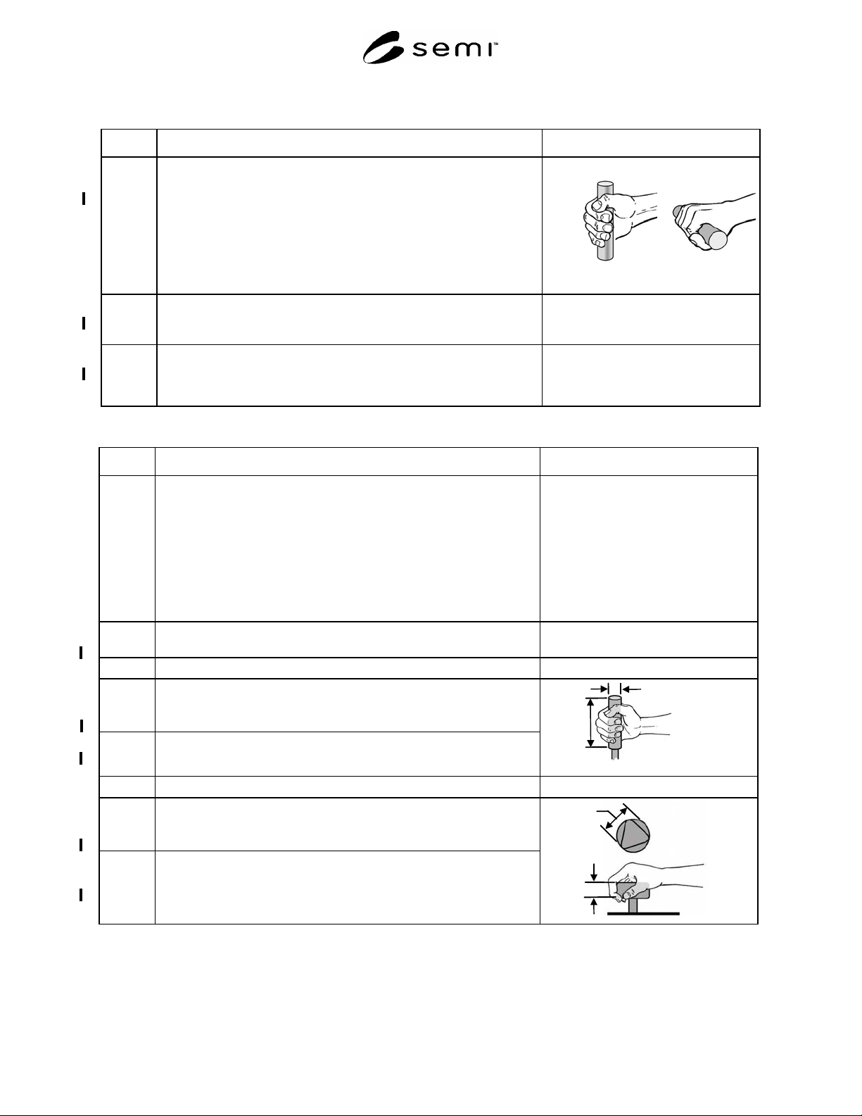
5.2 Hand grip(s) shall allow for a full “power grip” similar to grabbing a rung
on a ladder or holding a pistol.
Acceptance criterion: allows for a full power grip in either pronated (palm
facing down) or neutral (handshake position) posture.
NOTE A: Acceptable handle types include cylindrical, circular,
triangular, or enclosed.
NOTE B: See §6 for handle design recommendations.
Power Grips
5.3 Single hand lift force
Acceptance criterion: maximum 37.8 N (8.5 lbf). This value includes a
15% capacity reduction due to cleanroom glove use.
5.4 Two hand lift force
Acceptance criterion: maximum 64.5 N (14.5 lbf). This value includes a
15% capacity reduction due to cleanroom glove use.
Section 6: Handle Design
Section Indicator Figure
6.0 (Handle dimensions are correct for use of bare hand or use of typical
cleanroom gloves).
NOTE A: A recommended practice for selecting a handle design is to
first determine the force requirements before choosing a
handle design that is best suited for the intended forces,
motions and environment. Handle design recommendations
for various hand forces and handgrips are located in ¶¶6.2–
6.6.
NOTE B: Handles should anticipate the use of gloved hands.
6.1
Handle Surface finish:
Acceptance criterion: all edges radiused
6.2
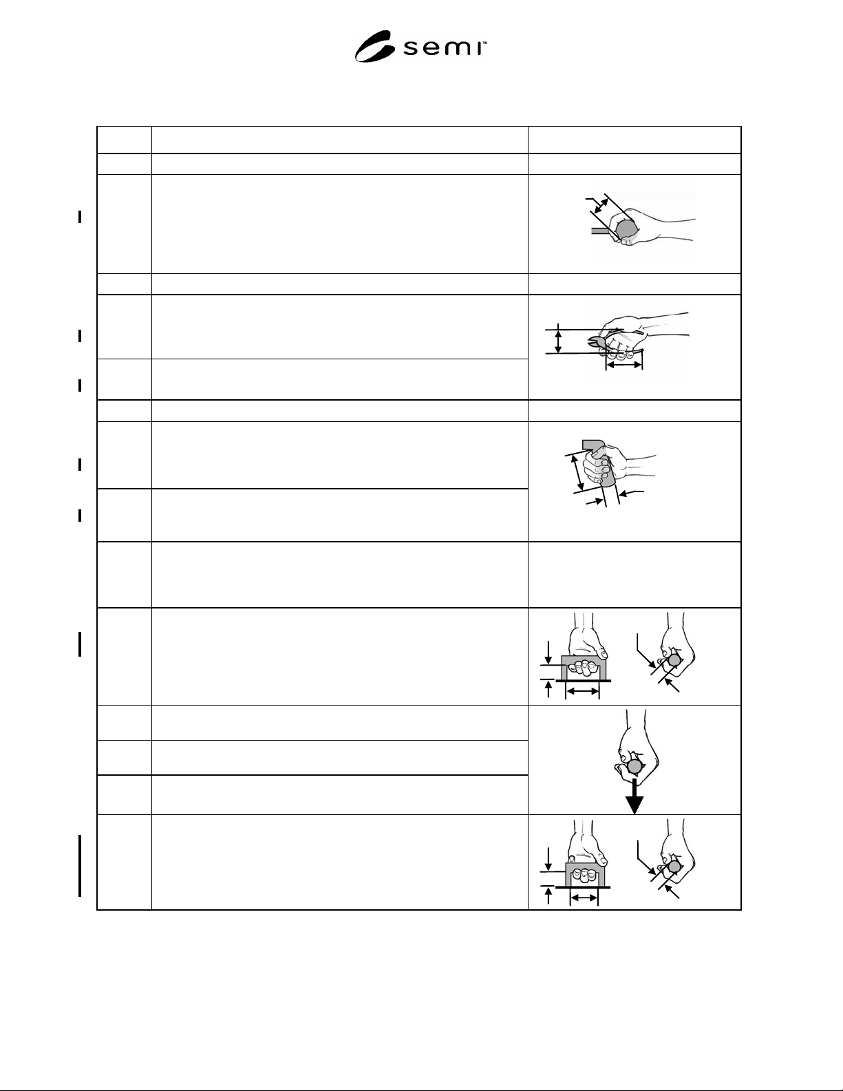
Cylindrical handle
6.2.1
Cylindrical handle diameter (D).
Acceptance criteria: maximum 38 mm (1.5 in.)
minimum 25 mm (1.0 in.)
6.2.2
Cylindrical handle length (L)
Acceptance criterion: minimum 127 mm (5.0 in.)
Length
Diameter
6.3
Circular or triangular handle
6.3.1
Circular or triangular handle diameter (D)
Acceptance criteria: maximum 90 mm (3.5 in.)
minimum 50 mm (2.0 in.)
6.3.2
Circular or triangular handle height (thickness) (H)
Acceptance criteria: maximum 25 mm (1 in.)
minimum 19 mm (0.75 in.)
Thickness
Diamete
r
SEMI S8-0705 © SEMI 1995, 2005 46
Section 6: Handle Design
Section Indicator Figure
6.4
Ball handle
6.4.1
Ball handle diameter
Acceptance criteria: maximum 63 mm (2.5in.)
minimum 19 mm (1.5 in.)
Diameter
6.5
Pliers handle
6.5.1
Pliers handle grip span (S)
Acceptance criteria: maximum 89 mm (3.5in.) open
minimum 38 mm (1.5 in.) closed
6.5.2
Pliers handle grip length (L)
Acceptance criterion: minimum 127 mm (5 in.)
Handle
S
p
an
Handle
Len
g
th
6.6 Pistol grip handle
6.6.1 Pistol grip handle diameter (D)
Acceptance criteria: maximum 63 mm (2.5 in.)
minimum 38mm (1.5 in.)
6.6.2 Pistol grip handle length (L)
Acceptance criterion: minimum 127 mm (5.0 in.)
Length
Diameter
6.7 Enclosed handles
NOTE: Handle diameter refers to the surface of the handle presented
to the inside of the curled fingers. Enclosed handles need not
be made solely from cylindrical stock.
6.7.1 Enclosed handle, full power grip (suitcase handle)
Width (W): minimum 127 mm (5.0 in.)
Depth (D): minimum 45 mm (1.75 in.)
Diameter (d): maximum 25 mm (1.0 in.)
Width
Depth
Diameter
6.7.1.1 Diameter requiring no more than 71 N (16 lbf.) force
Diameter: minimum 6.3 mm (0.25 in.)
6.7.1.2 Diameter requiring no more than 89 N (20 lbf.) force
Diameter: minimum 13 mm (0.50 in.)
6.7.1.3 Diameter requiring no more than 200 N (40 lbf.) force
Diameter: minimum 19 mm (0.75 in.)
6.7.2 Enclosed handle, three fingers
Width (W): minimum 90 mm (3.5 in.)
Depth (D): minimum 38 mm (1.5 in.)
Diameter (d): minimum 6.3 mm (0.25 in.)
Force: maximum 71 N (16 lbf)
Width
Depth
Diameter