semi合集-English.pdf - 第59页
SEMI E6-0303 © SEMI 1982, 2003 5 9.3.10 Equipment Comments (100J) — Enter any comments nec essary to clari fy or add to inform ation given fo r this e quipment. 9.3.11 Equipment Supplier Name (100K) — Enter legal name of…

SEMI E6-0303 © SEMI 1982, 2003 4
8.4.3.1 There should be a unique Connection Number,
or identifier, for every connection. If a utility type has
more than one connection, each point of connection
should have a number.
8.4.3.2 A consistent Connection Numbering system
should be used to identify all connections in all
documents relating to the equipment.
8.4.4 The Connection Label is the third column, C, of
each data sheet 400-1000. The Connection Label and
Connection Number system should provide a clear link
between all documentation and the actual connection on
the equipment.
8.4.5 Utility Type is the fourth column, D, of each data
sheet 400–1000. A consistent Utility Type naming
convention should be used to identify the utility types
in all documents relating to the equipment. (For
example SEMI E52 should be used for defining gases.)
8.4.6 Fitting Size, Fitting Material, and Fitting Type
(found in most data sheets) refer to connectors or
fittings on the equipment; such that the equipment
purchaser can identify and procure the matching
connector for fit up to the equipment. Do not define the
facilities side connectors in these data sheets.
8.4.7 Comments are the last column of each data sheet
400–1000. All comments should be entered in a single
cell at the end of the row corresponding to the
connection requiring comment. Comments may need to
be repeated in comments cell for each similar
connection. General comments for equipment model
may be included in the comments cell in table 100, or if
specific to an equipment component in tables 200 or
300.
8.5 Data Collection
8.5.1 Actual measured utility data, based upon
representative operating conditions, is preferred over
unverified estimates or calculations.
8.5.2 All data measures of flow rate, chemical waste,
dump volumes, etc., should be based upon the
supplier’s standard process and production rate.
8.5.3 All specifications and measurements in data
sheets 400–1000 should be at the equipment point of
connection.
8.5.4 If utility consumption data entered into the data
sheet is not measured data, note in the comments cell
how the data was obtained. For example: calculated
data or estimated data.
8.6 The following sections, 9 through 19, include
recommendations on how to complete each individual
data sheet.
9 Equipment Identification Data Sheet
9.1 Include in Data Sheet 100, Equipment
Identification the requested information for general
equipment identifiers, descriptions, installation
documentation references and data sheet set revision.
9.2 The 10 data sheets that follow the equipment
identification data sheet are specific to equipment
component and connection requirements (for example
gases, exhaust, vacuum, etc.) and describe the needs of
the equipment identified in the equipment identification
data sheet.
9.3 Data Sheet 100, Equipment Identification contains
the following items.
NOTE 4: Many of the items in data sheet 100 should be
included in a header on each page of any SEMI E6 Data print
outs or reports.
9.3.1 Equipment Install Data ID (100A) — Enter a
unique reference number (or file name) as a reference
for this equipment installation data set which includes
all data sheets 100 through 1000.
9.3.2 Equipment Install Data Revision (100B) — Enter
the revision number (or code) for this equipment
installation data set.
9.3.3 Equipment Install Data Revision Date (100C) —
Enter the data of the last revision to this equipment
installation data set.
9.3.4 SEMI Standard Name and Revision Date (100D)
— Enter the name and revision of the version of SEMI
E6 that this data set is in conformance with. For
example SEMI E6-96.
9.3.5 Equipment Name (100E) — Enter the name for
this equipment.
9.3.6 Equipment Model Number (100F) — Enter the
equipment supplier’s model number for the equipment.
9.3.7 Generic Process Type (100G) — Enter the
generic process type the equipment was designed to
perform. For example metal etch, Al PVD, or copper
CMP.
9.3.8 Wafer Size (100H) — Enter in mm the size of
wafer the equipment was designed to process. For
example: 200 or 300.
9.3.9 Number of Equipment Components (100I) —
Enter the number of stand-alone modules provided by
the supplier that together make the equipment process
capable. Typically one for the mainframe plus one for
each piece of supplier provided support equipment.
These equipment components will be named in column
A of data sheets 200 and 300. This number will be the
rows required in data sheet 200 and 300.
SEMI E6-0303 © SEMI 1982, 2003 5
9.3.10 Equipment Comments (100J) — Enter any
comments necessary to clarify or add to information
given for this equipment.
9.3.11 Equipment Supplier Name (100K) — Enter legal
name of equipment supplier.
9.3.12 Equipment Supplier Street Address (100L) —
Enter legal address for equipment supplier.
9.3.13 Equipment Supplier City, State, Country, Mail
Code (100M) — Enter city, state, country, and mail
code corresponding to legal address.
9.3.14 Equipment Supplier Phone (100N) — Enter
phone number corresponding to legal address.
9.3.15 Administrative Interface Information Reference
(100O) — Enter reference for document containing
relevant supplier and purchaser contacts. (See Section
7.1.1 and Related Information 1)
9.3.16 Optional Order Specific Data Purchasing
Company (100P) — If needed enter name of company
purchasing the equipment.
9.3.17 Optional Order Specific Data Purchase Order
Number (100Q) — If needed enter the P.O. Number
issued by the purchaser for procuring the equipment.
9.3.18 Optional Order Specific Data Purchaser’s
Equipment ID (100R) — If needed enter the number
used by the purchaser to track the purchased equipment.
9.3.19 Optional Order Specific Data Equipment Serial
Number (100S) — If needed enter the number issued by
the supplier and used to track the equipment as
purchased.
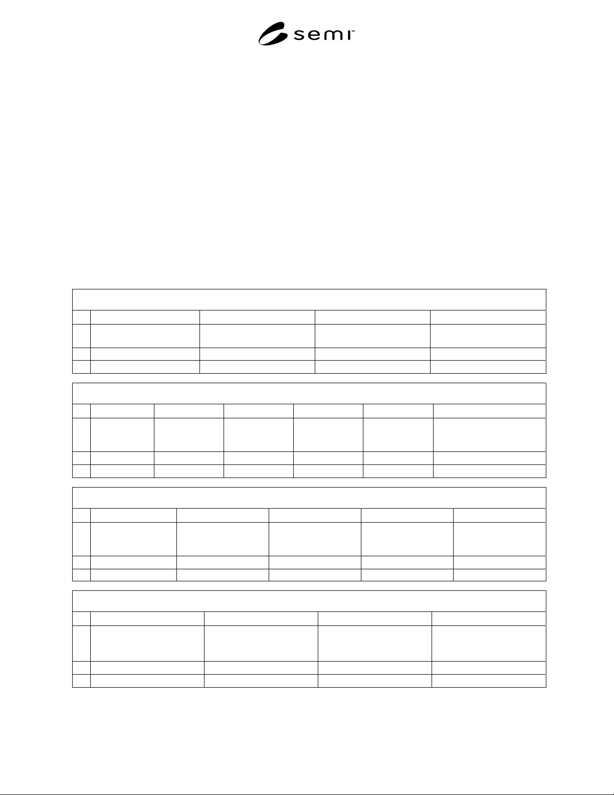
Data Sheet 100 – Equipment Identification (See SEMI E6 Section 9)
100 Equipment Identification
A B C D
1
Equipment Install Data ID Equipment Install Data
Revision
Equipment Install Data
Revision Date
SEMI Standard Name and
Revision Date
2 text text text text
3 SEMI E6 mmyy
100 Equipment Identification
E F G H I J
1
Equipment
Name
Equipment
Model Number
Generic
Process Type
Wafer Size Number of
Equipment
Components
Equipment Comments
2 text text text mm # text
3
100 Equipment Identification
K L M N O
1
Equipment Supplier
Name
Equipment Supplier
Street Address
Equipment Supplier
City, State, Country,
Mail Code
Equipment Supplier
Phone
Administrative
Interface Information
Reference
2
text text text text text
3
100 Equipment Identification
P Q R S
1
Optional
Order Specific Data
Purchasing Company
Optional
Order Specific Data
Purchase Order Number
Optional
Order Specific Data
Purchaser’s Equipment ID
Optional
Order Specific Data
Equipment Serial Number
2 text text text text
3

SEMI E6-0303 © SEMI 1982, 2003 6
10 Environmental Conditions Data Sheet
10.1 Include in Data Sheet 200, Environmental
Conditions, requested information for the
environmental conditions necessary to operate the
equipment such as room temperature, room humidity,
room cleanliness, heat loading, and vibration. Include
only conditions for area surrounding the equipment, do
not refer to internally controlled specifications for
integrated minienvironments, chambers, or lenses, etc.
10.2 Data Sheet 200, Environmental Conditions,
contains the following items.
10.2.1 Equipment Component (200A) — Enter the
name of the equipment component for the data in this
row. The same component names should be used in the
following data sheets.
10.2.2 Maximum Installation Distance from Mainframe
(200B) — Enter the maximum line of sight or straight
line distance between the mainframe and equipment
component. Also, indicate the limiting factors for this
distance. For example: 6 meters, user routing
constraints may cause distance to be significantly less.
10.2.3 Minimum Cleanroom Classification (200C) —
Enter the minimum cleanroom classification that
defines the cleanroom environment necessary for
equipment to operate correctly.
10.2.4 Cleanroom Classification Standard (200D) —
Enter a reference for the cleanroom classification
standard used to specify the cleanroom class in 200C.
For example: Fed Std 209E or ISO 14644.
10.2.5 Target Room Temperature (200E) — Enter the
optimal temperature setting within the minimum and
maximum ranges for the room where the equipment is
located.
10.2.6 Minimum Room Temperature (200F) — Enter
the minimum room temperature for the equipment to
operate correctly.
10.2.7 Maximum Room Temperature (200G) — Enter
the maximum room temperature for the equipment to
operate correctly.
10.2.8 Room Temperature Fluctuation (200H) — Enter
the maximum room temperature change during one
hour for the equipment to operate correctly.
10.2.9 Heat Loading Idle Average (200I) — Enter the
average heat flow rate in idle condition into the room
where the equipment component is located. Do not
include heat removed by other means such as process
cooling water or exhaust. The room should be at target
temperature and humidity.
10.2.10 Heat Loading Process Average (200J) — Enter
the average heat flow rate during the processing cycle
into the room where the equipment component is
located. Do not include heat removed by other means
such as process cooling water or exhaust. The room
should be at target temperature and humidity.
10.2.11 Target Room Relative Humidity (200K) —
Enter the optimal relative humidity at the target
temperature for the room where the equipment is
located.
10.2.12 Minimum Room Relative Humidity (200L) —
Enter the minimum relative humidity at the target room
temperature for the equipment to operate correctly.
10.2.13 Maximum Room Relative Humidity (200M) —
Enter the maximum relative humidity at the target room
temperature for the equipment to operate correctly.
10.2.14 Room Relative Humidity Fluctuation (200N) —
Enter the maximum relative humidity change during
one hour for the equipment to operate correctly.
10.2.15 Vibration Sensitivity (200O) — Enter the
vibration requirements or reference a document
specifying the ambient vibration sensitivity and ambient
acoustic noise sensitivity of the equipment. Include in
reference material the description of methods used such
as displacement, 1/3 octave band analysis, accelerance,
maximum velocity at frequency, maximum ambient
sound pressure levels, etc.
10.2.16 Vibration Generation (200P) — Enter the
vibration generated by the equipment that stimulates the
mounting structure or reference a document defining
the equipment generated dynamic loads (at the support
points defined in the floor loading diagram—see
Section 11.2.10) such as impulse force magnitudes in
the front-to-rear direction, etc. Include in reference
material the description of methods used such as
spectral accelerometer measurements of the equipment
mounted on a pedestal of specified stiffness, etc.
Include equipment-generated acoustic noise, such as the
sound pressure level spectra radiated outward from the
equipment enclosure.
10.2.17 Other Vibrations Requirements (200Q) —
Enter or reference any other equipment support
vibration requirements such as support pedestal
stiffness requirements in all three directions, coupled
mass requirements, or minimum building structural
stiffness (three axis x, y, z) requirements.
NOTE 5: Vibration sensitivity and generation values for
dynamic loads and motions should be specified in the three
directions: up and down (z), front to back (y), and side to side
(x).