semi合集-English.pdf - 第782页
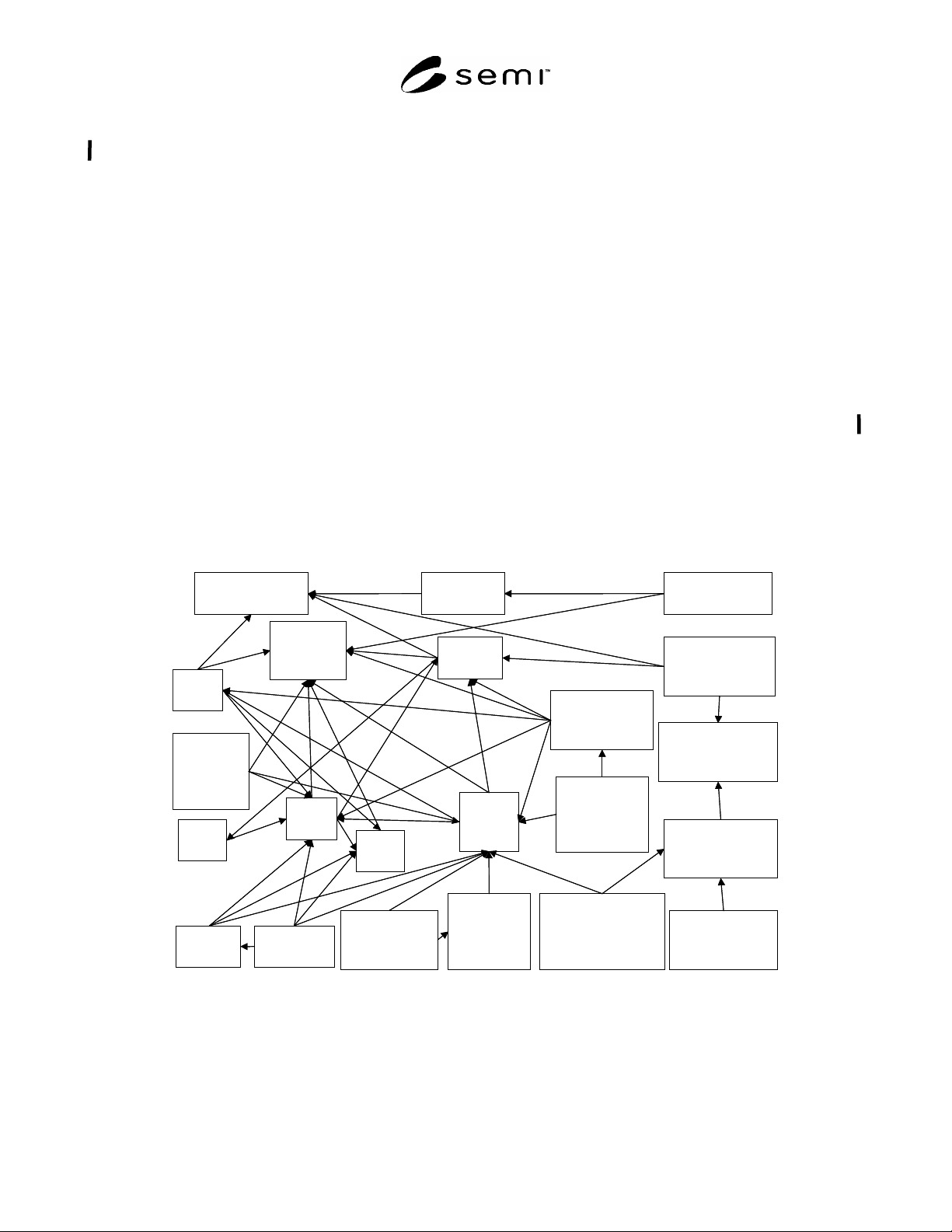
SEMI E104-0303 © SEMI 2000, 2003 18 APPENDIX 4 AEROSOL TRANSPORT A ND AEROSOL SAMPLING NOTICE : The material in this appendix is an official part of SEMI E104 and was approved by full letter ballot procedures on July 28,…

SEMI E104-0303 © SEMI 2000, 2003 17
A3-5 Aerosol Neutralization
A3-5.1 When dispersing the suspension, the particles
are charged. This surface charge should be removed
after drying the aerosol flow to avoid electrostatic
interactions with each other or the line walls. With the
help of the discharging distance of an electrostatic
neutralizer, the aerosol is exposed to a bipolar ion
source. Some electrostatic neutralizers may produce a
large number of ultra-fine particles which will combine
with the calibration aerosol and affects the signal-to-
noise-ratio of the LPPD and the reference particle
counter.
A3-6 Aerosol Size Separation
A3-6.1 When calibrating with ultra-fine particles, a
particle size separation might be necessary to remove
the residue particles and agglomerates. An electrostatic
classifier is most effective for particle sizes less than 1
µm. This instrument electrically charges the incoming
aerosol. With electrostatic deflection, it separates
selected particles of one mobility. The residue particles
and the larger aggregate particles would be stripped out
of the particle stream consisting of the desired polymer
particles. To charge the aerosol, the electrostatic
classifier uses a radioactive neutralizer. The aerosol
exiting the instrument will contain singly charged
particles. This low charge level makes the use of an
additional aerosol neutralizer unnecessary.
Nevertheless, conductive tubing should be used
between the aerosol generator and the LPPD and
reference particle counter to minimize electrostatic
particle loss.
A3-7 Aerosol Dilution
A3-7.1 The particle concentration of the aerosol
generated by the nebulizer might be too high. The
aerosol should be further diluted to achieve the required
concentration and to avoid coincidence errors. The
dilution could be executed with a mixing chamber in
which the aerosol is mixed with zero gas. The internal
chamber pressure should be stable and very close to
ambient atmospheric pressure at operational flow rates.
The spatial particle distribution in the exiting aerosol
should be as homogenous as possible.

SEMI E104-0303 © SEMI 2000, 2003 18
APPENDIX 4
AEROSOL TRANSPORT AND AEROSOL SAMPLING
NOTICE: The material in this appendix is an official part of SEMI E104 and was approved by full letter ballot
procedures on July 28, 2000 by the European Regional Standards Committee.
A4-1 Aerosol Transport
A4-1.1 Aerosol loss in lines occurs both for small and
larger particles. Larger particles (approximately 5 µm
and larger) are lost as a result of gravitational settling in
horizontal lines and inertial effects in all lines. Smaller
particles are lost to the line walls by diffusion and by
electrostatic charge effects.
A4-1.2 A limitation of particle loss could be achieved
with tubing as short and as straight as possible with no
bends with a radius of curvature less than 100 mm. The
tubing of the calibration setup should be smooth,
conductive, and electrically grounded. Stainless,
polished steel for rigid lines and Polyurethane or
polyvinyl chloride for flexible lines is found acceptable
for handling most aerosols with low electrostatic
particle loss. If long transit lines are required, they
should be sized to permit a Reynolds number in the
range of 5,000 to 25,000 at the sample flow rate to
minimize particle residence time in the tubing without
causing excessive turbulence at high flow rates.
A4-2 Aerosol Sample Acquisition
A4-2.1 The term isokinetic sampling often is used in
aerosol measurement and characterization. Isokinetic
sampling of particles in a moving aerosol is performed
by matching the sample probe inlet velocity (flow speed
and
direction) to the velocity of the moving aerosol. At
velocities less than 15 m/s, anisokinetic sampling errors
are negligible for most particles smaller than
approximately 5 µm. Losses of larger particles might be
significant. The larger the particle, the larger the loss
due to inertial effects. Isokinetic sampling is not
possible in environmental conditions with varying
velocity, motionless air, and turbulent, random, or non-
unidirectional flow. For better sampling inlet efficiency,
isokinetic or at least isoaxial sampling is recommended
at calibration.
NOTICE: SEMI makes no warranties or
representations as to the suitability of the standards set
forth herein for any particular application. The
determination of the suitability of the standard is solely
the responsibility of the user. Users are cautioned to
refer to manufacturer' s instructions, product labels,
product data sheets, and other relevant literature,
respecting any materials or equipment mentioned
herein. These standards are subject to change without
notice.
By publications of this standard, Semiconductor
Equipment and Materials International (SEMI) takes no
position respecting the validity of any patent rights or
copyrights asserted in connection with any items
mentioned in this standard. Users of this standard are
expressly advised that determination of any such patent
rights or copyrights, and the risk of infringement of
such rights are entirely their own responsibility.
Copyright by SEMI® (Semiconductor Equipment and Materials
International), 3081 Zanker Road, San Jose, CA 95134. Reproduction o
f
the contents in whole or in part is forbidden without express written
consent of SEMI.
SEMI E106-1104 © SEMI 2000, 2004 1
SEMI E106-1104
OVERVIEW GUIDE TO SEMI STANDARDS FOR PHYSICAL
INTERFACES AND CARRIERS FOR 300 mm WAFERS
This guide was technically approved by the Global Physical Interfaces & Carriers Committee and is the direct
responsibility of the North American Physical Interfaces & Carriers Committee. Current edition approved by
the North American Regional Standards Committee on July 11, 2004 and August 16, 2004. Initially
available at www.semi.org September 2004; to be published November 2004. Originally published October
2000; previously published March 2003. This document replaces SEMI PR6-0200 in its entirety.
1 Purpose
1.1 This document is intended to help users and
suppliers of 300 mm carriers and production equipment
to understand the complex interdependencies among the
SEMI standards for 300 mm physical interfaces and
carriers and to determine which standards apply to
which products. As shown in Figure 1, these standards
are highly inter-related, have many complex
dependencies, and inherit a numbering system (from
legacy 200 mm standards) that is non-intuitive.
2 Scope
2.1 This document describes how the SEMI standards
for 300 mm physical interfaces and carriers work
together. This document also clarifies the requirements
(direct and indirect) on suppliers of each product, and
suggests how users see these standards and options.
NOTICE: This standard does not purport to address
safety issues, if any, associated with its use. It is the
responsibility of the users of this standard to establish
appropriate safety and health practices and determine
the applicability of regulatory or other limitations prior
to use.
M1.15, M8, M28
Wafer
E25
Cluster - Tool
Module Access
E26.1
Radial Cluster -
Tool Footprint
E21.1
Cluster
-
Tool
Module Interface
G77
Frame Cassette
E22.1
Cluster - Tool
End
Effector
M31
FOSB
G74
Tape Frame
E103
SWIF
E47.1
FOUP
E62
FIMS
E15.1
Load
Port
E63
BOLTS-M
E92
Bolts
-
Light
E83
PGV Docking
Flange
E64
Cart
Docking
Interface
E72
Equipment
Footprint, Height,
and Weight
E1.9
Cassette
E85
AMHS
Interoperabiity
E84
Carrier
Handoff
Parallel I/O
E57
Kinematic
Coupling
E110
Indicator/
switch
Placement
M1.15, M8, M28
Wafer
E25
Cluster - Tool
Module Access
E26.1
Radial Cluster -
Tool Footprint
E21.1
Cluster
-
Tool
Module Interface
G77
Frame Cassette
E22.1
Cluster - Tool
End
Effector
M31
FOSB
G74
Tape Frame
E103
SWIF
E47.1
E62
FIMS
E15.1
Load
Port
E92
Bolts
-
Light
E83
PGV Docking
Flange
E64
Cart
Docking
Interface
E72
Equipment
Footprint, Height,
and Weight
E1.9
Cassette
E85
AMHS
Interoperabiity
E84
Carrier
Handoff
Parallel I/O
E57
Kinematic
Coupling
E110
Indicator/
switch
Placement
Figure 1
Complex Relationships and Dependencies Among 300 mm Standards