semi合集-English.pdf - 第2227页
SEMI E58-0703 © SEMI 1997, 2003 8 1.7.6.1 The colum ns labeled Req/Ind a nd Rsp/C onf link the parameters to the direction of the message. The message sent by the initiator is called the “Request”. The receiver terms thi…
SEMI E58-0703 © SEMI 1997, 2003 7
diagram of the states and the transitions between states,
and a state transition table. The diagram of the state
model uses the Harel State Chart notation. An overview
of this notation is presented in an appendix of SEMI
E30. The formal definition of this notation is presented
in Science of Computer Programming 8, “Statecharts:
A Visual Formalism for Complex Systems”, by D.
Harel, 1987.
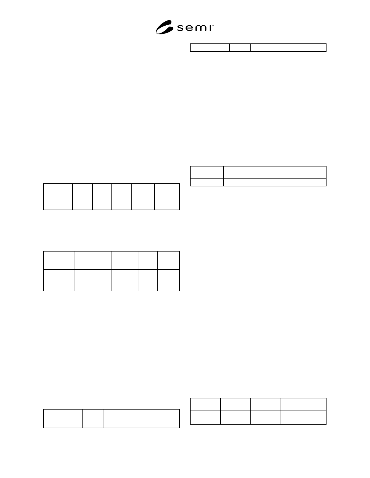
1.6.1 Transition tables are provided in conjunction
with the state diagrams to explicitly describe the nature
of each state transition. A transition table contains
columns for Transition #, Current State, Trigger, New
State, Action(s), and Comment. The “trigger” (column
3) for the transition occurs while in the “current” state.
The “actions” (column 5) includes a combination of 1)
actions taken upon exit of the current state, 2) actions
taken upon entry of the new state, and 3) actions taken
which are most closely associated with the transition.
No differentiation is made between these cases.
#
Current
State
Trigger
New
State
Action(s)
Comment
Transition #
1.7 Object Attribute Representation — The object
information models for standardized objects will be
supported by an attribute definition table with the
following column headings:
Attribute
Name
Definition
Access
Reqd
Form
The formal
text name of
the attribute.
Description of
the information
contained.
RO or RW Y or N (see
below)
1.7.1 The Access column uses RO (Read Only) or RW
(Read and Write) to indicate the access that users of the
service have to the attribute.
1.7.2 A ‘Y’ or ‘N’ in the Required (Reqd) column
indicates if this attribute must be supported in order to
meet fundamental compliance for the service.
1.7.3 The Form column is used to indicate the format
of the attribute (see Section 4 for definitions).
6.2 Service Message Representation
1.7.4 Service Resource Definition — A service
definition table defines the specific set of messages for
a given service resource, as shown in the following
table:
Message
Service Name
Type
Description
Message name N or R The intent of the service
1.7.4.1 Type can be either N = Notification or R =
Request.
1.7.4.2 Notification type messages are initiated by the
service provider and the provider does not expect to get
a response from the service user (consumer/subscriber).
1.7.4.3 Request messages are initiated by a service
user. Request messages ask for data or an activity from
the provider. Request messages expect a specific
response message (no presumption on the message
content).
1.7.5 Service Parameter Dictionary — A service
parameter dictionary table defines the parameters for
one or more services, as shown in the following table:
Parameter Description Form
Parameter X A parameter called X is B in A. Data type.
1.7.5.1 A row is provided in the table for each
parameter of the service. The first column contains the
name of the parameter. This is followed by columns
describing the form and contents of the corresponding
parameter.
1.7.5.2 The Form column is used to indicate the type
of data contained in a parameter (see Section 4 for
definitions).
1.7.5.3 The Description column in the Service
Parameter Dictionary table describes the meaning of the
parameter, the allowed values, and any
interrelationships with other parameters.
1.7.5.4 To prevent the definition of numerous
parameters named “XxxList”, this document adopts the
convention of referring to the list as “(List of) Xxx”. In
this case, the definition of the variable Xxx will be
given, not of the list. The term “list” indicates a
collection (or set) of zero or more items of the same
data type.
1.7.5.5 Where a list is used in both the request and the
response, the list order in the request is retained in the
response. A list must contain at least one element unless
zero elements are specifically allowed.
1.7.6 Service Message Definition — A service
message definition table defines the parameters used
in a service, as shown in the following table:
Parameter Req/Ind Rsp/Conf Description
Parameter X (see below) (see below) A description of the
parameter.
SEMI E58-0703 © SEMI 1997, 2003
8
1.7.6.1 The columns labeled Req/Ind and Rsp/Conf
link the parameters to the direction of the message. The
message sent by the initiator is called the “Request”.
The receiver terms this message the “Indication”. The
receiver may then send a “Response”, which the
original sender terms the “Confirmation”.
1.7.6.2 The following codes appear in the Req/Ind and
Rsp/Conf columns and are used in the definition of the
parameters (e.g., how each parameter is used in each
direction):
“M” - Mandatory parameter — Must be given a
valid value.
“C” - Conditional parameter — May be defined in
some circumstances and undefined in others.
Whether a value is given may be a completely
optional or may depend on the value of other
parameters.
“U” - User-defined parameter
“-” — The parameter is not used.
“=” — (For response only) Indicates that the value
of this parameter in the response must match that in
the primary (if defined).
7 Overview
1.8 This section provides an overview of how
ARAMS will be applied and the capabilities that
ARAMS defines.
1.9 Systems that are used to track equipment
performance should be based on SEMI E10’s
definitions of the six basic equipment states. The
tracking systems typically rely on factory personnel to
manually enter SEMI E10 state changes. Individual
factories may have further company-specific and/or
facilities-specific refinements of the states. For
example, the basic equipment state may be
“unscheduled downtime” with a refinement of “waiting
for parts”. In addition to entering a state change, the
operator (who may be the production operator, a
process engineer, an equipment engineer, or a supplier
field service engineer) may select from a pre-defined
set of behaviors (symptoms) that prompted the change
of state, such as “smoke observed”.
1.10 Specifications provided by ARAMS are intended
to support the integration of equipment systems with
factory tracking systems. For this purpose, equipment
needs to be cognizant of the ARAMS states and
substates, must know its current state, and must follow
common rules for determining if equipment-initiated
transitions can be made. In addition, the user needs to
be able to interact with the tracking system at either the
host system’s console or the equipment’s operator
console. This requires that the operator be able to enter
certain information at the equipment’s console: a new
state or substate request, and specific observed behavior
that prompted the request. The host system is then
notified that a change in state has occurred.
1.11 Integrated systems are able to provide more
accurate data for those state changes than the equipment
alone is able to detect. While the user is still required to
initiate state changes for other conditions, this can be
accomplished either directly at the equipment’s console
or remotely at the host tracking system terminal.
1.12 Exchange of information is accomplished
through standardization of the meaning and form of
data and the specification of the message services for
the exchange. ARAMS provides generic definitions for
the common substates described in SEMI E10. ARAMS
also defines two tables and the message services
required for the equipment and host to exchange tables.
The first table contains a set of ARAMS substate
definitions (an ARAMS code identifying the substate)
and a corresponding description. The second table
defines a set of symptoms with a numeric symptom
identifier and a corresponding description.
1.13 While the above discussion assumes that the
equipment is interacting with host systems, the
ARAMS state model only requires interactions with a
“user”, which might be either a local operator or a host
system.
8 State Models
1.14 This section defines the formal state model for
ARAMS, called the ARAMS State Model, which is
required for ARAMS compliance. To clarify the
relationships between this state model and the
equipment’s operations, it introduces a second state
model, called the General Equipment Operations
Model, which is used for purposes of illustration. The
General Equipment Operations Model is assumed to
exist in some form but is not required for ARAMS
compliance.
1.14.1 This document follows the convention of using
upper-case to denote the formal names of states.
Informal references may use lower case. For example,
the ARAMS states SCHEDULED DOWNTIME and
UNSCHEDULED DOWNTIME may be referred to as
downtime states.
1.14.2 Detailed requirements for equipment behavior
are provided in Section 16.
NOTE 6: Although the equipment is unable to detect a
condition of no power, it is able to detect when the
INITIALIZING state has been entered and is able to
differentiate between a hard reset (Transition 6) and a soft re-
boot (Transition 5).
SEMI E58-0703 © SEMI 1997, 2003 9
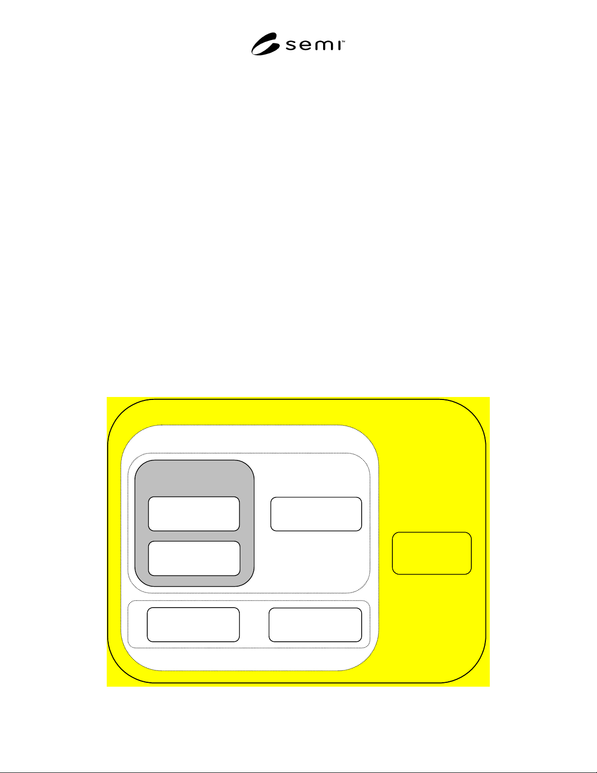
8.1 SEMI E10 Equipment States — Figure 1 contains a
diagram of SEMI E10 equipment states using the Harel
notation. SEMI E10 divides total time into six basic
states: PRODUCTIVE, ENGINEERING, STANDBY,
SCHEDULED DOWNTIME, UNSCHEDULED
DOWNTIME, and NON-SCHEDULED TIME. These
six states are shown in Figure 1 with solid lines.
1.14.3 OPERATIONS TIME, UPTIME,
DOWNTIME, and MANUFACTURING TIME are
derived by grouping states defined in SEMI E10 and
are useful for classification purposes, but formally they
are not considered as SEMI E10 equipment states. Time
in these groupings can be derived by summing the time
in their corresponding states, based on Figure 1.
NOTE 7: Figure 1 uses shadings to show derived states. It is
not intended as a formal state model.
1.14.4 MANUFACTURING TIME includes time
spent in PRODUCTIVE and STANDBY. UPTIME
includes the time spent in MANUFACTURING TIME
and ENGINEERING. DOWNTIME includes the time
spent in SCHEDULED DOWNTIME and
UNSCHEDULED DOWNTIME.
1.14.5 In SEMI E10, precise rules governing state
transitions are not required. The ARAMS model, in
contrast, is intended to be used by automated equipment
capable of detecting internal conditions. Conditions for
each valid state transition are defined, both those
initiated by equipment and those determined by
interactions between the user and the equipment.
8.2 ARAMS State Model Definition — This section
contains the formal definition of the ARAMS State
Model, consisting of three parts:
• A diagram of the ARAMS State Model (Figure 2),
using Harel notation,
• a description of each state and the behavior of the
equipment within that state, and
• a table of transitions (Table 1) showing the
previous state before the transition, the trigger for
the transition, the new state after the transition, a
description of any actions to be taken upon entry,
and comments concerning the new state.
8.2.1 ARAMS State Model Diagram — Figure 2
contains the diagram of the ARAMS State Model.
8.2.2 Descriptions of ARAMS States — This section
provides brief descriptions of the basic states for model
completeness.
NOTE 8: These are informal descriptions included for the
completeness of the ARAMS State Model. They do not
replace the formal definitions in SEMI E10.
TOTAL TIME
OPERATIONS TIME
NON-
SCHEDULED
TIME
STANDBY
PRODUCTIVE
MANUFACTURING
TIME
UPTIME
ENGINEERING
SCHEDULED
DOWNTIME
UNSCHEDULED
DOWNTIME
Figure 1