semi合集-English.pdf - 第3351页
SEMI E132-0305 © SEMI 2004, 2005 4 7.4.2 Kind — Specifies whethe r the argument is an ‘in’, ‘out ’, or ‘error’ a rgument for the operation. ‘er ror’ arguments al ways function as ‘out’ argum ents, but indicate that the o…
SEMI E132-0305 © SEMI 2004, 2005 3
7 Conventions
7.1 Unified Modeling Language (UML) Notation — All class and sequence diagrams in this standard make use of
the Unified Modeling Language notation.
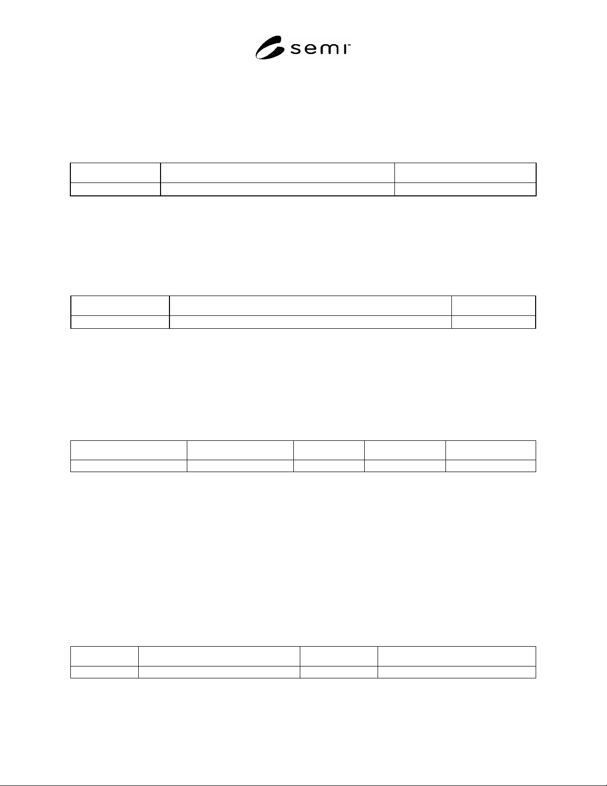
7.2 Attribute Tables — The table below provides an example of the tables used to list and describe attributes of
classes defined in this specification.
Table 1 Attribute Table Format
Attribute Name Definition Form
See list below.
7.2.1 Form — Defines the data type of the attribute. The terms used to describe data types used in this column are
defined in the SEMI Compilation of Terms, or are included as part of the specification. Refer to the compilation of
terms for the definition of SEMI type name meanings.
7.2.2 Association Tables — The table below provides an example of the tables used to list and describe associations
between classes defined in this specification.
Table 2 Association Table Format
Association Role Name Definition Comments
7.2.2.1 Association Role Name — The name of the association role being specified.
7.2.2.2 Definition — Describes the function or purpose of the association.
7.2.2.3 Comments — Any additional comments or notes regarding the association.
7.3 Operation Definition Tables — The table below provides an example of the tables used to list and describe the
interface operations defined in this specification.
Table 3 Operation Definition
Operation Description Type Requestor/Sender Responder/Receiver
See list below.
7.3.1 Operation — Specifies the name of the operation.
7.3.2 Type — Specifies the messaging semantics of the operation. Only Request-Response (RR) and Fire-and-
Forget (FF) semantics are used in this specification.
7.3.3 Requestor/Sender — For RR semantics, identifies the entity that makes the request, for FF semantics,
identifies the entity that sends the message. Can be ‘Client’, ‘Admin’, or ‘Equipment’. Client can be any of the
applications communicating to equipment compliant to this specification.
7.3.4 Responder/Receiver — For RR semantics, identifies the entity that responds to the request, for FF semantics,
identifies the entity that receives the message. Can be ‘Client’, ‘Admin’, or ‘Equipment’.
7.4 Operation Argument Definition Table — The table below provides an example of the tables used to list and
describe arguments for interface operations defined in this specification.
Table 4 Operation Argument Definitions
Argument Description Kind Form
See list below. See list below.
7.4.1 Argument — Specifies the name of the argument.
SEMI E132-0305 © SEMI 2004, 2005 4
7.4.2 Kind — Specifies whether the argument is an ‘in’, ‘out’, or ‘error’ argument for the operation. ‘error’
arguments always function as ‘out’ arguments, but indicate that the operation did not complete successfully. Not all
errors possible for a specific operation will be listed, only select typical ones are.
7.4.3 Form — Defines the data type of the argument. The terms used to describe data types in this column are
defined in the SEMI Compilation of Terms, or are included as part of the specification. Refer to the compilation of
terms for the definition of SEMI type name meanings.
8 Background
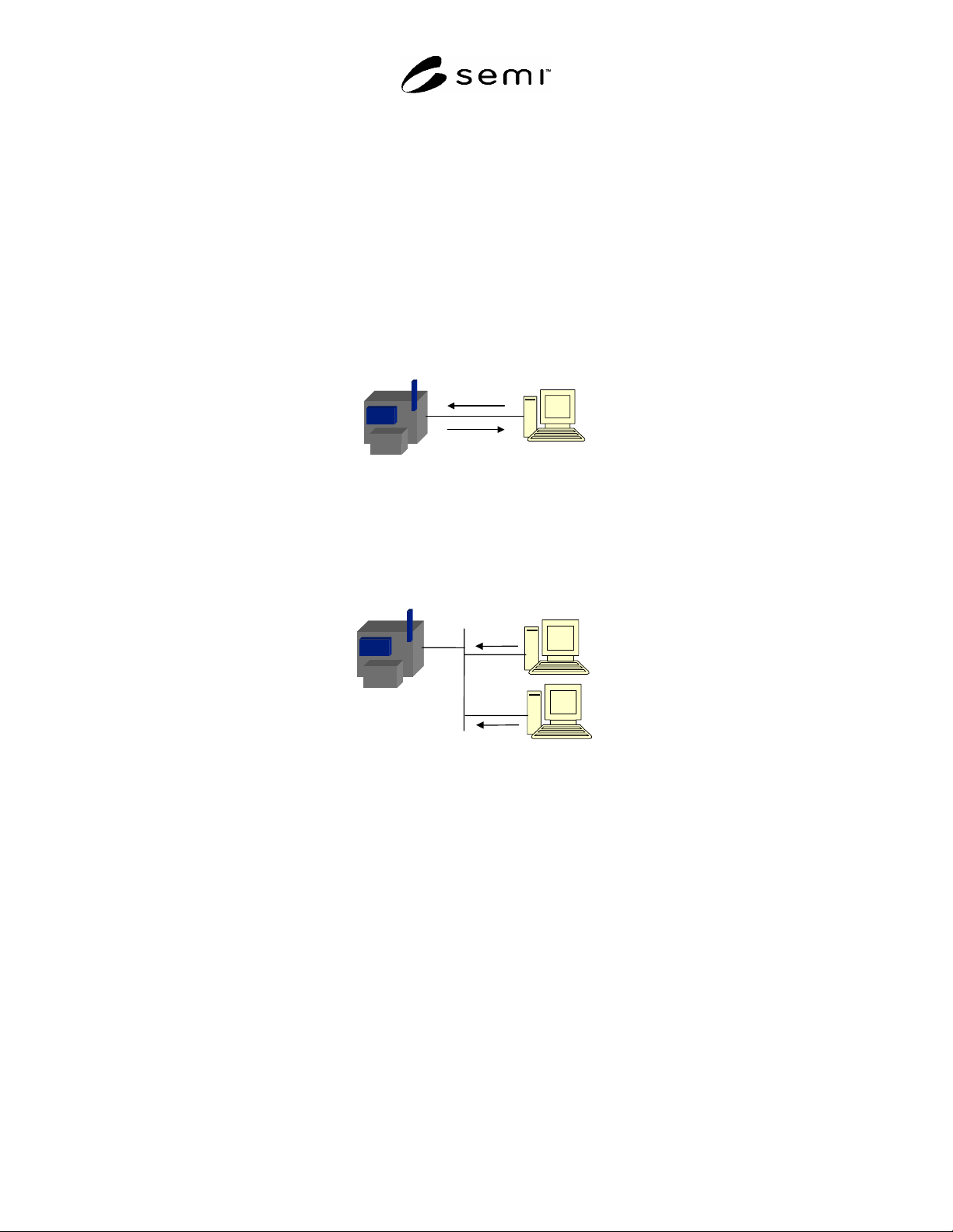
8.1 In conventional semiconductor equipment communication, such as that defined by SEMI E30, it is assumed that
only a single client application can gain access to the equipment for communication. This assumption was valid
when the physical transport medium was based on a serial cable connection to the equipment. In such an
environment, it is possible to ensure that only a single client application is permitted to interface with the equipment
by only providing the serial connection to the machine on which the application runs.
consoleconsole
Execute process
program
acknowledge
Figure 1
Equipment Communication via Serial Cable
8.2 As equipment communication moves from a serial cable medium to Ethernet, it becomes possible for any client
on the network to send requests to the equipment, provided there is a path from the client node to the equipment.
Without taking specific measures to secure communication with the equipment, it is not possible to ensure that only
authorized clients are permitted to communicate with the equipment.
consoleconsole
A
uthorized Data Collection
Request
Unauthorized Data Collection
Request
Figure 2
Equipment Communication via Ethernet
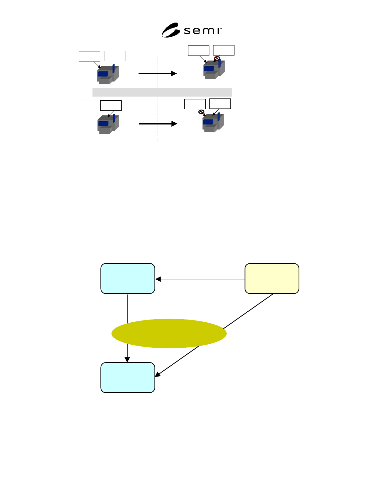
8.3 Even if the equipment accepts only a single connection request from the network, it is still vulnerable to a race
condition among any clients that attempt to connect. This results in a “first-come, first-served” policy in which the
first client to attempt a connection with the equipment is granted access, even if that client is not authorized to
communicate with that specific equipment. Such an environment is insufficient for providing adequate protection of
equipment resources.
SEMI E132-0305 © SEMI 2004, 2005 5
consoleconsole
consoleconsole
consoleconsole
consoleconsole
The HSMS-SS approach: only accept first connect request
wrong
client
right
client
wrong
client
right
client
wrong
client
right
client
wrong
client
right
client
Right client attempts to connect
first, is granted access
Right client attempts to connect
second, is denied access
Figure 3
First-come First-served Communication
8.4 A more secure technique to ensure that only authorized clients are allowed to utilize equipment resources is to
require clients to first prove their identity to the equipment. If the equipment knows a client’s identity, then the
equipment may be able to assume that the client is authorized to proceed with further requests.
9 Overview
9.1 This standard defines a mechanism for clients of manufacturing equipment to authenticate to the equipment prior
to any subsequent communication. To facilitate this, both the authentication procedure itself and a means for
establishing client identities with the equipment beforehand must be defined. This standard also defines a flexible
scheme for authorization and mechanisms to support a centralized administration model.
9.2 Central Administration Model — A conceptual view of a central security administration model is presented in
Figure 4 below.
Credentials/Authorizations Mgmt
Client Credentials/
Authorizations
Authenticate
Security
Admin
Equipment
Client
Authentication/
Authorization Interface
Credentials/Authorizations Mgmt
Client Credentials/
Authorizations
Authenticate
Security
Admin
Equipment
Client
Authentication/
Authorization Interface
Figure 4
Security Administration Model
9.2.1 Security Admin — The security admin issues client credentials, establishes client authorizations and possibly
client credentials on the equipment, defines custom roles and their authorizations. Client credentials are identifying
information for the client. The security admin manages equipment authorizations and client credentials using an
administration interface defined in this specification. The interface between security admin and client to