semi合集-English.pdf - 第7845页
SEMI T13-1104 © SEMI 2004 5 8 Overvie w 8.1 Die Trace Capability — Econom ic growth around the world ma kes it possible to get entered into semiconductor manufacturi ng business and advanced electronics business w hich u…
SEMI T13-1104 © SEMI 2004 4
6.4.1 Service Definition
6.4.1.1 A service definition table defines the specific set of messages for a given service resource, as shown in the
following table:
Message Service Name Type Description
6.4.1.2 Type can be either “N” = Notification or “R” = Request & Response.
6.4.1.3 Notification type messages are initiated by the service provider (e.g., the equipment) and the provider does
not expect to get a response from the service user. Request messages are initiated by a service user (e.g., the host).
Request messages ask for data or an activity from the provider. Request messages expect a specific response
message (no presumption on the message content).
6.4.2 Service Parameter Dictionary
6.4.2.1 A service parameter dictionary table defines the description, format and its possible value for parameters
used by services, as shown in the following table:
Parameter Name Description Format: Possible Value
6.4.2.2 A row is provided in the table for each parameter of a service.
6.4.3 Service Message Definition
6.4.3.1 A service message definition table defines the parameters used in a service, as shown in the following table:
Parameter Req/Ind Res/Cnf Comment
6.4.3.2 The columns labeled REQ/IND and RSP/CNF link the parameters to the direction of the message. The
message sent by the initiator is called the “Request”. The receiver terms this message the “Indication” or the request.
The receiver may then send a “Response” which the original sender terms the “Confirmation”.
6.4.3.3 The following codes appear in the REQ/IND and RSP/CNF columns and are used in the definition of the
parameters (eg., how each parameter is used in each direction):
M Mandatory Parameter — Must be given a valid value.
C Conditional Parameter — May be defined in some circumstances and undefined in others. Whether a value is
given may be completely optional or may depend on the value of the other parameter.
U User-Defined Parameter.
- The parameter is not used.
= (For response only.) Indicates that the value of this parameter in the response must match that in the primary (if
defined).
NOTE 1: Concatenated words are often used for names of class, attribute, service and data. However they are official,
sometimes separated words may be preferred in figures and explanatory sentences for readability even they are no differences.
7 General Requirements
7.1 Identification Means — Equipment and other computer or software have to have some means to identify entities
that appear in this document.
7.2 Communication Means — Each entity on equipment and other computer or software has to have some electric
communication means to transact.
SEMI T13-1104 © SEMI 2004 5
8 Overview
8.1 Die Trace Capability — Economic growth around the world makes it possible to get entered into semiconductor
manufacturing business and advanced electronics business which uses semiconductor devices. The number of
semiconductor manufacturing countries and/or companies including subsidiaries and branch divisions is growing.
Procurement by e-commerce makes it easy to purchase semiconductor devices and electronics parts as application of
the devices from emerging companies in wide and distant areas. Suppliers of such devices and parts are required to
have device tracking facilities or die tracing capabilities to reduce security risks, perform quality assurance, improve
quality engineering and some other purpose depending on products.
8.2 Wide Area Communication — Such electronics as cell phones and television sets consist of many
semiconductor devices. They are decomposed into circuit boards, display module, operation panel unit and so on.
Most of such subcomponents also consist of semiconductor devices. They are supplied by semiconductor
manufacturers, set makers or third party suppliers. Tracking semiconductor devices or die tracing does not just
happen in semiconductor manufacturing fab. Close communication with assembly works including print circuit
board (PCB) suppliers and set makers is expected.
8.3 Range of Die Tracing — If traceability expectation were only for confirmation of producer and producing
country, this standard would address backend processes and PCB assembly line. Industries around semiconductor
manufacturing, e.g. automobile and car electronics industries, anticipate more than secure components. To address
that, this document extends the range of specification not only for assembly but also for wafer processes. Some
specific process data including metrology and inspection may be included in target data for die tracing.
8.4 Die Trace Data — As described above, data traced for a die doesn’t come from just one specific process or a
piece of equipment. Die information is required to be traced on each key equipment. Otherwise it doesn’t make
sense, in other words, tracing system doesn’t work as a whole. Storage for Die Trace Data may or may not be
distributed.
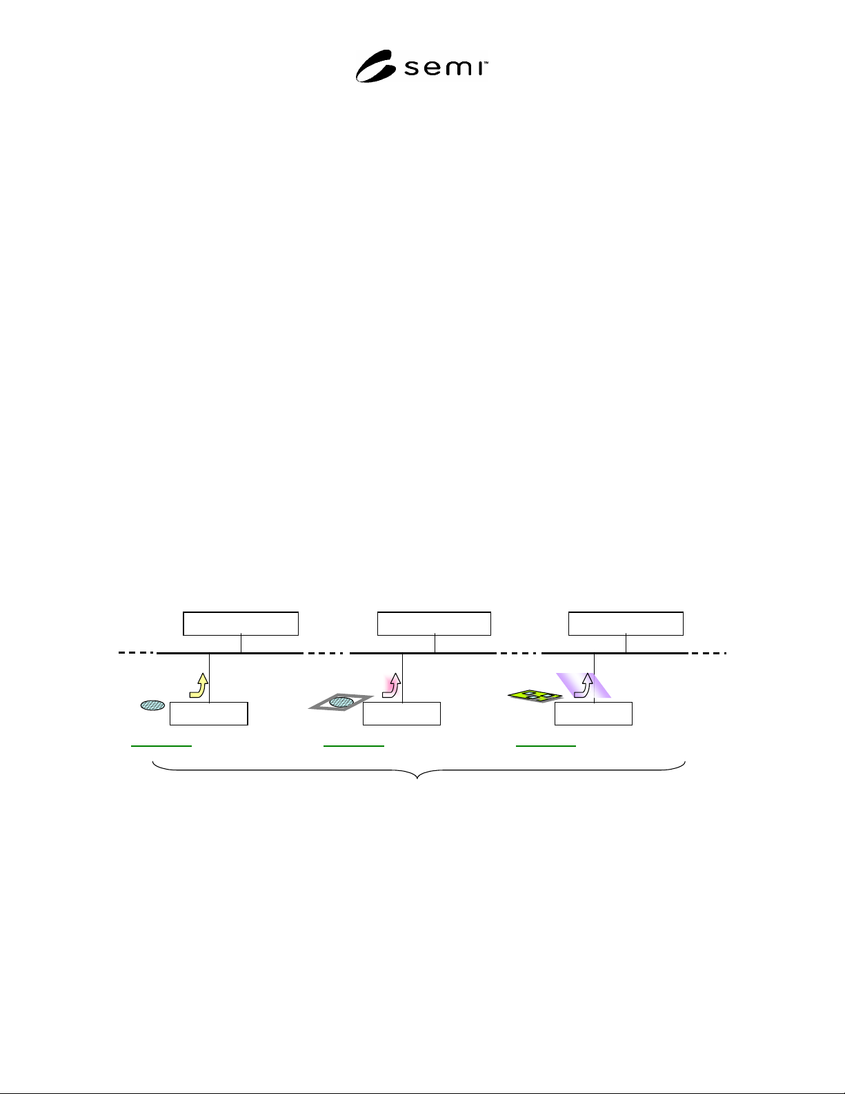
8.5 Variety of Die Trace Data — Tracers collect various kinds of data for die tracing. They may be collation
information of pick & place history from dicing film to lead frame, electric test information for sorting dice or
metrology data on the wafer to which a die belongs. They are just examples of variety of Die Trace Data. Their
generic format can not be specified and unified central tracing system may not be realistic.
dice
Die Trace Data
Trace Data Storage
Equipment-P
Process-A
Material-X
dice
Die Trace Data
Trace Data Storage
Equipment-Q
Process-B
Material-X
dice
Die Trace Data
Trace Data Storage
Equipment-R
Process-C
Material-X
Same Material on Different Equipment types for Different Processes
Figure 1
Example of Die Trace Data on Key Equipment
8.6 Data Source of Die Trace Data — Most Die Trace Data are reported by equipment because die tracing tracks
what happens on a die for process. The things that happen are not for equipment control, process control nor
performance tracking done with execution. But they are for logging to certify the pedigree of a product or to track
back when some serious problem is detected on a product or prevent further damage to application of the product. In
this sense, Die Trace Data may be a part of or summary of MES data, or some calculated data. Equipment may not
be the data source in these cases.
8.7 Data Taxonomy — Die Trace Data can be categorized in various ways: by data source, data type, data form,
semantics and so on. The other classification criteria may be geometric information, deviation of process settings,
SEMI T13-1104 © SEMI 2004 6
metrology data, inspection results, test results, and sorting information. If dice on such substrate as wafer and PCB
are processed, all dice share data for the substrate. This case a part of data for a die links to the substrate data. If a
group of dice or substrates which is referred to as a lot is processed at a time or in the same environment, die trace
data for one of the dice links to the lot.
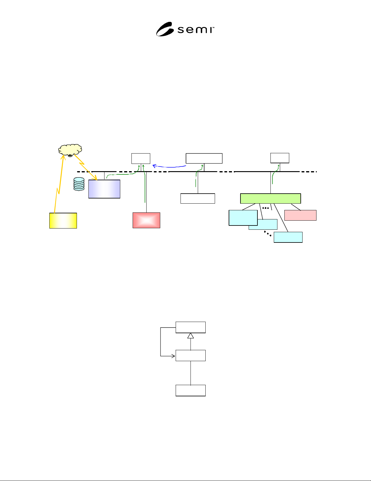
8.8 Die Trace System and its Clients — Die Trace System keeps collecting expected Die Trace Data on Equipment
or some other entities in a fab. A Client asks the system to make specific information for die tracing about one or
more dice. Client may give some fault information to the system to find out the cause of the fault. When the system
discovers a potential problem, it may notify an alert. Die Tracer is a closest entrance to Die Trace System.
8.9 Tracer and Machine — To reduce ambiguity or burdensome discussion and to make a process conspicuous, this
document highlights die trace data of a process or on a piece of equipment from the ensemble of data. In this aspect
data tracking entity, or a snapshot of the system, is referred to as ‘Tracer’ and entity to execute the process is called
as ‘Machine’ to discriminate from physical equipment.
VIT
VIT
ask
Material /
Acceptance
Database
Die Trace
Data (DTD)
WIP
Computer
Machine
Die Trace Data
Tracer
Defect Analysis System
Inspection
Tool (VIT)
Review Tool
Tracer / Client
Supplier
Database
Tracer
Die Trace
Data (DTD)
Die Tr ace
Data (DTD)
Figure 2
Example of Tracers with/without Machine
9 Basic Concepts
9.1 Domain Analysis and Object Based Modeling — To model and design complicated system or to have shared
specification of a part of system which is used widely in deferent applications, some sophisticated methodologies are
required. Analyzing problem domain by object oriented paradigm is one of the best practices to be taken. Because
this technology is frequently used in many SEMI standards, there is no confusion if this document follows the way.
Client
collects
1..*
1
..*
asks
Tracer
Machine
0..*
Figure 3
Die Trace Cell Model