semi合集-English.pdf - 第6322页
SEMI G63-95 © SEMI 1995, 2002 3 12.1.7 Die shear stren gth in N (k gf)/die un it (complete data or an averag e) 12.1.7.1 S tandard dev iation w hen n um ber of specim ens tested is adequate. 12.1.8 Tem perature in hot di…
SEMI G63-95 © SEMI 1995, 2002 2
10 Procedure
10.1 Set a test specimen on the die shear tester.
10.2 Confirm that the die contact tool contacts the die
side in half of the area or more and that the die contact
tool does not touch the fillet.
10.3 Shear the specimen with the tester.
10.4 Record the strength.
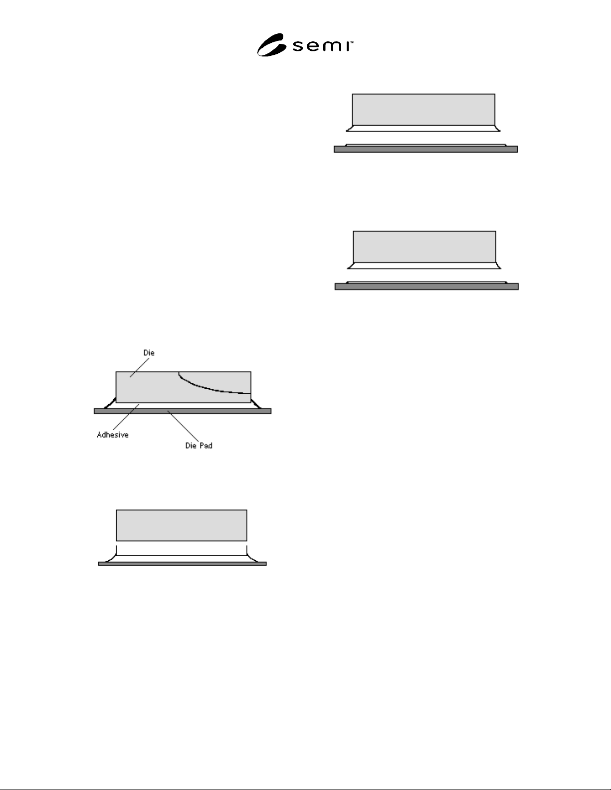
10.5 Observe failed parts and classify in the following
modes:
Mode 1: Die breakage
Mode 2: Adhesive failure between die and die
attach paste
Mode 3: Cohesive failure
Mode 4: Adhesive failure between die attach paste
and substrate
Mode 5: Substrate deformation
Figure 1
Mode 1 — Break-In Die
Figure 2
Mode 2 — Interface Failure: Die-to-Adhesives
Figure 3
Mode 3 — Break-In Adhesives
Figure 4
Mode 4 — Interface Failure:Adhesives-to-Die Pad
NOTE 4: In the case of hot die shear strength testing, the hot
temperature shall be agreed between user and supplier.
Procedure is as follows:
1. Set and raise the hot plate temperature
2. Confirm that actual temperature is within the range
of ± 10° C at the set temperature.
3. Put a specimen on the hot plate and follow Section
10.3 after 10 to 20 seconds.
11 Calculation of Result
11.1 Average strength and standard deviation shall be
calculated if required.
12 Report
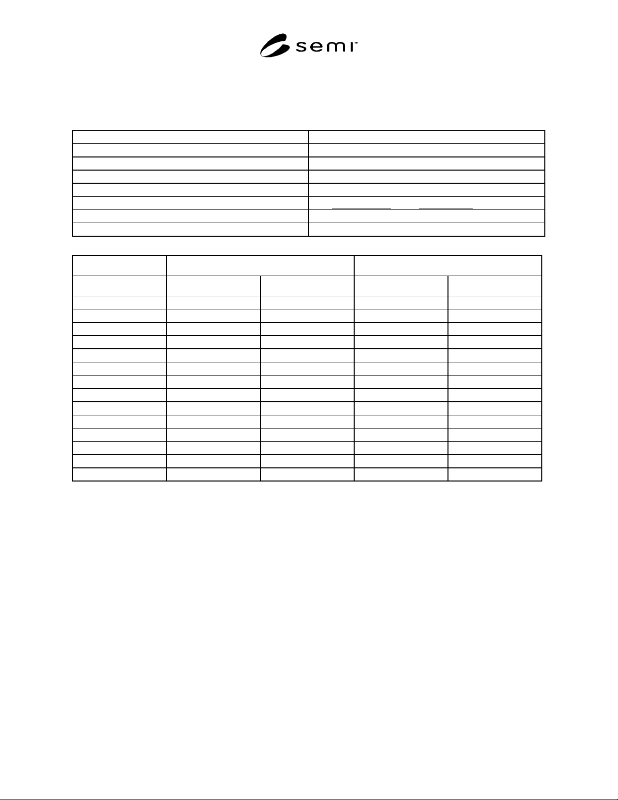
12.1 The following information shall be reported in the
attached form:
12.1.1 Type of die attach paste
12.1.2 Type of leadframe and leadframe plating
12.1.3 Thickness of die and surface condition (attached
side) of the die.
12.1.4 Cure schedule and atmosphere (air or nitrogen)
12.1.5 Information about die attach paste thickness,
dispense weight, or bond line thickness before and after
cure.
12.1.6 Die shear speed
SEMI G63-95 © SEMI 1995, 2002 3
12.1.7 Die shear strength in N (kgf)/die unit (complete
data or an average)
12.1.7.1 Standard deviation when number of specimens
tested is adequate.
12.1.8 Temperature in hot die shear testing.
Die Attach Paste (Material)
Leadframe Type
Leadframe Plating
Die Thickness
Die Surface Condition
Cure Schedule Time Temp. in air or N
2
Thickness or Dispense Weight
Shear Speed
RT Hot Temperature
Strength (N (kgf)/chip) Failure Mode Strength (N (kgf)/chip) Failure Mode
Sample 1
Sample 2
Sample 3
Sample 4
Sample 5
Sample 6
Sample 7
Sample 8
Sample 9
Sample 10
Sample 11
Sample 12
Average
Standard Deviation
SEMI X##-#### © SEMI 2001 4
APPENDIX 1
NOTE: The material in this appendix is an official part of SEMI G63 and was approved by full letter ballot
procedures in 1995.
A1-1 Purpose
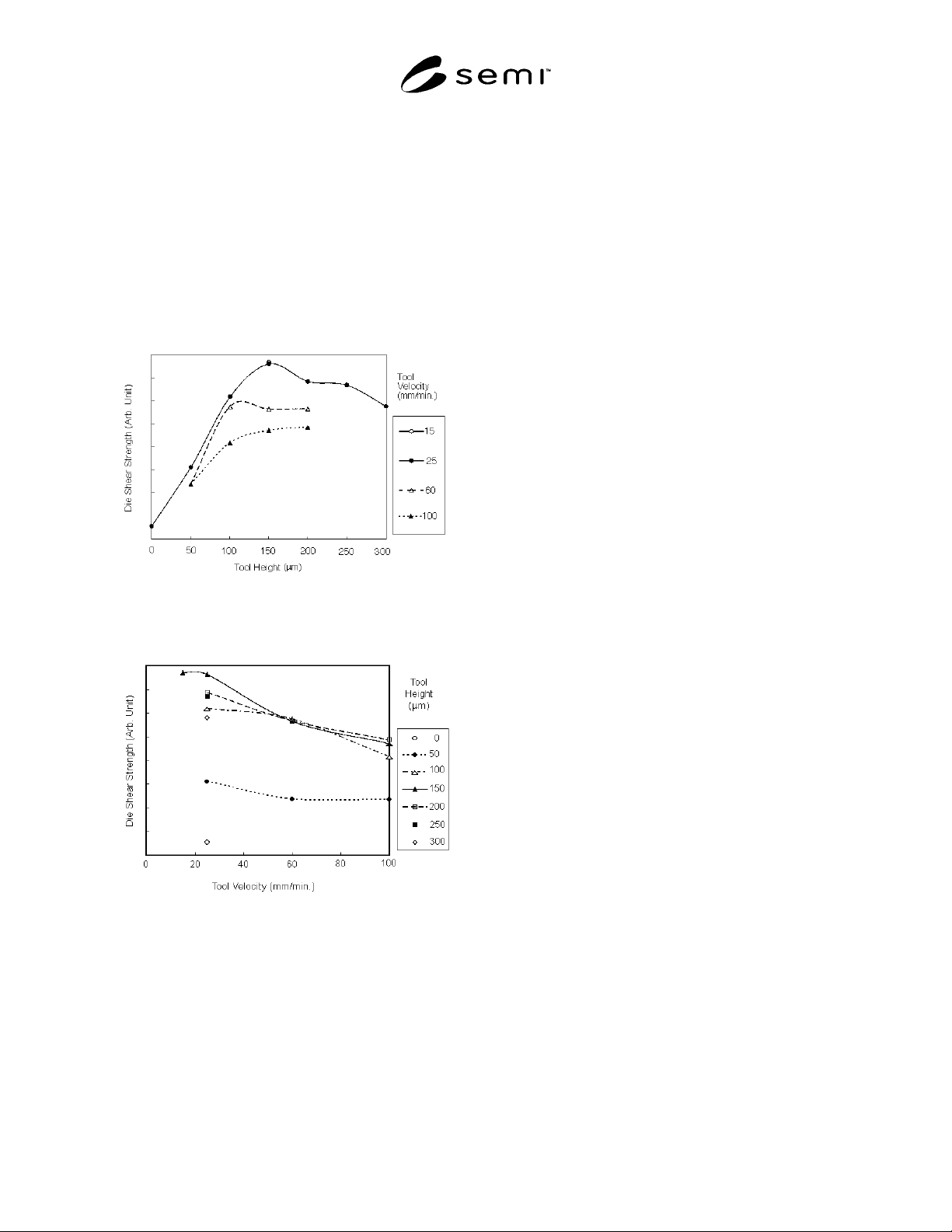
The purpose of this appendix is to indicate that speed
and height of the die contact tool affect die shear
strength results.
A1-2 Test Results
Figure A1-1
Tool Velocity Test Results
Figure A1-2
Tool Height Test Results
A1-2.1 Summary
A1-2.1.1 Shear Speed
a. Some adhesive might yield variable results due to
the relationship of the shear speed and failure
speed.
b. Some equipment with high shear speed could yield
low strength due to poor sensitivity at the peak of
the load.
A1-2.1.2 Height of the Die Contact Tool
a. In case of low height, fillet level might affect the
strength.
b. In case of high height, a variable result might be
obtained since the tool pulls the die and it tears the
adhesive.
NOTICE: SEMI makes no warranties or
representations as to the suitability of the standards set
forth herein for any particular application. The
determination of the suitability of the standard is solely
the responsibility of the user. Users are cautioned to
refer to manufacturer’s instructions, product labels,
product data sheets, and other relevant literature
respecting any materials mentioned herein. These
standards are subject to change without notice.
The user’s attention is called to the possibility that
compliance with this standard may require use of
copyrighted material or of an invention covered by
patent rights. By publication of this standard, SEMI
takes no position respecting the validity of any patent
rights or copyrights asserted in connection with any
item mentioned in this standard. Users of this standard
are expressly advised that determination of any such
patent rights or copyrights, and the risk of infringement
of such rights, are entirely their responsibility.
Copyright by SEMI® (Semiconductor Equipment and Materials
International), 3081 Zanker Road, San Jose, CA 95134. Reproduction o
f
the contents in whole or in part is forbidden without express writte
n
consent of SEMI.